Production apparatus of monodisperse particle and production process of monodisperse particle and monodisperse particle produced by the process

a technology of monodisperse particle and production process, which is applied in the direction of granulation using vibration, furnace, transportation and packaging, etc., can solve the problems of insufficient measurement of the suitability of monodisperse particle for various applications, difficult to control particle size widely, and production of particle siz

Inactive Publication Date: 2002-07-11
KAWASAKI CORP KK
View PDF0 Cites 99 Cited by
  • Summary
  • Abstract
  • Description
  • Claims
  • Application Information

AI Technical Summary

Problems solved by technology

However, in conventional process, classification operation is inevitable, and further it is generally difficult to control the particle size widely, that is, to obtain the monodisperse particle of desired particle size.
Further, in the PREP process, rotational stability of electric poles limits the production of the particle to the diameter of approximately 100 .mu.m.
However, it is not sufficient to determine suitability of the monodisperse particle for various kinds of applications by the only fact that high-accurate spherical monodisperse particles can be produced.
In other words, unless the multi-purpose monodisperse particles suitable for various applications by itself can be definite, it is difficult to produce the monodisperse particle industrially and cheaply.
For this reason, there exists a costly problem for industrial application of the monodisperse particle to various fields.
Where the diameter of the supply pipe is less than 100 .mu.m, it is difficult to supply the flowable material to the retention container for flowable material, and impossible and inconvenient to continuously, stably eject.
On the other hand, where the diameter of the supply pipe exceeds 900 .mu.m, escape of the flowable material to the supply pipe becomes large and displacement of the diaphram or the cylinder rod becomes very large, and then the flow of the flowable material to the orifice becomes unstable, therefore, it becomes difficult to continuously and stably eject, as a result, it is not preferable.
Where the k is less than 0.5, it is difficult to supply the flowable material to the retention container for flowable material, and impossible and inconvenient to continuously, stably eject.
On the other hand, where the K exceeds 0.95, escape of the flowable material to the supply pipe becomes large and displacement of the diaphram or the cylinder rod becomes very large, and then the flow of the flowable material to the orifice becomes unstable, therefore, it becomes difficult to continuously and stably eject, as a result, it is not preferable.
Further, intervention of foam into the material is not allowed, therefore, it is possible to high-efficiently apply energy provided from outside to the flowable material.
On the other hand, when the difference in pressure P between internal pressure of the material container (Pi) and external pressure of the material container (Po) exceeds the limit difference in pressure Pc, the flowable material flows down from the orifice by its weight and then the production control becomes difficult.
In this case, if the standard deviation exceeds 2 .mu.m, it is difficult to laminate other plane body with close contact on the plane body on which the particles in 100 to 300 .mu.m are arranged in plane, two dimensionally, in this sense, it is difficult to apply to the area in which uniformity of the component particle diameter is particularly important, in this point, there are applications in which it can not be applied as monodisperse particle, therefore, it can not be widely used and inconvenient.
In here, if the standard deviation exceeds 5 .mu.m, the flowability lowers and the filling density becomes small as well as variation in the component particles becomes excessive, and become nonuniform as aggregation, as a result, there are applications in which it can not be applied as monodisperse particle, therefore, it can not be widely used and inconvenient.
As a result, there is inconvenience that classification operation is separately required.
Further, if the sphericity exceeds 2.5%, the component particles become irregular, and there are applications in which it can not be applied, therefore, it can not be widely used and inconvenient.
In here, if the standard deviation exceeds 5 .mu.m, variation in the component particles becomes excessive, as a result, there are applications in which it can not be applied as monodisperse particle, therefore, it can not be widely used and inconvenient, and further, if the sphericity exceeds 2.5%, the component particles become irregular, and there are applications in which it can not be applied, therefore, it can not be widely used and inconvenient.
In this case, however, if the slurry by its own weight falls toward the recovery part C, it is difficult to efficiently and continuously produce the ceramics spherical monodisperse particles.
In the above, when the difference in pressure between the internal pressure (Pi) of the slurry retention part b and external pressure (Po) of the slurry retention part b is less than 0, this is a factor to obstruct the supply through the supply pipe 21c, whereas, when the difference in pressure between the internal pressure (Pi) of the slurry retention part b and external pressure (Po) of the slurry retention part exceeds the limit difference in pressure, the slurry flows down from the orifice by its own weight, therefore, it is difficult to control production.
In this state, they are not cooled sufficiently, therefore, condensing and deforming occurs, and then complete shaped metallic glass particle sphere is not obtained, however, it is possible to check the possibility for production conditions.
Whereas, when the difference in pressure between the internal pressure (Pi) of the scrucible 26 and external pressure (Po) of the scrucible 26 exceeds the limit difference in pressure, the material liquid flows down from the orifice by its own weight, therefore, it is difficult to control production.

Method used


Image

  • Production apparatus of monodisperse particle and production process of monodisperse particle and monodisperse particle produced by the process
  • Production apparatus of monodisperse particle and production process of monodisperse particle and monodisperse particle produced by the process
  • Production apparatus of monodisperse particle and production process of monodisperse particle and monodisperse particle produced by the process

Examples


example 1

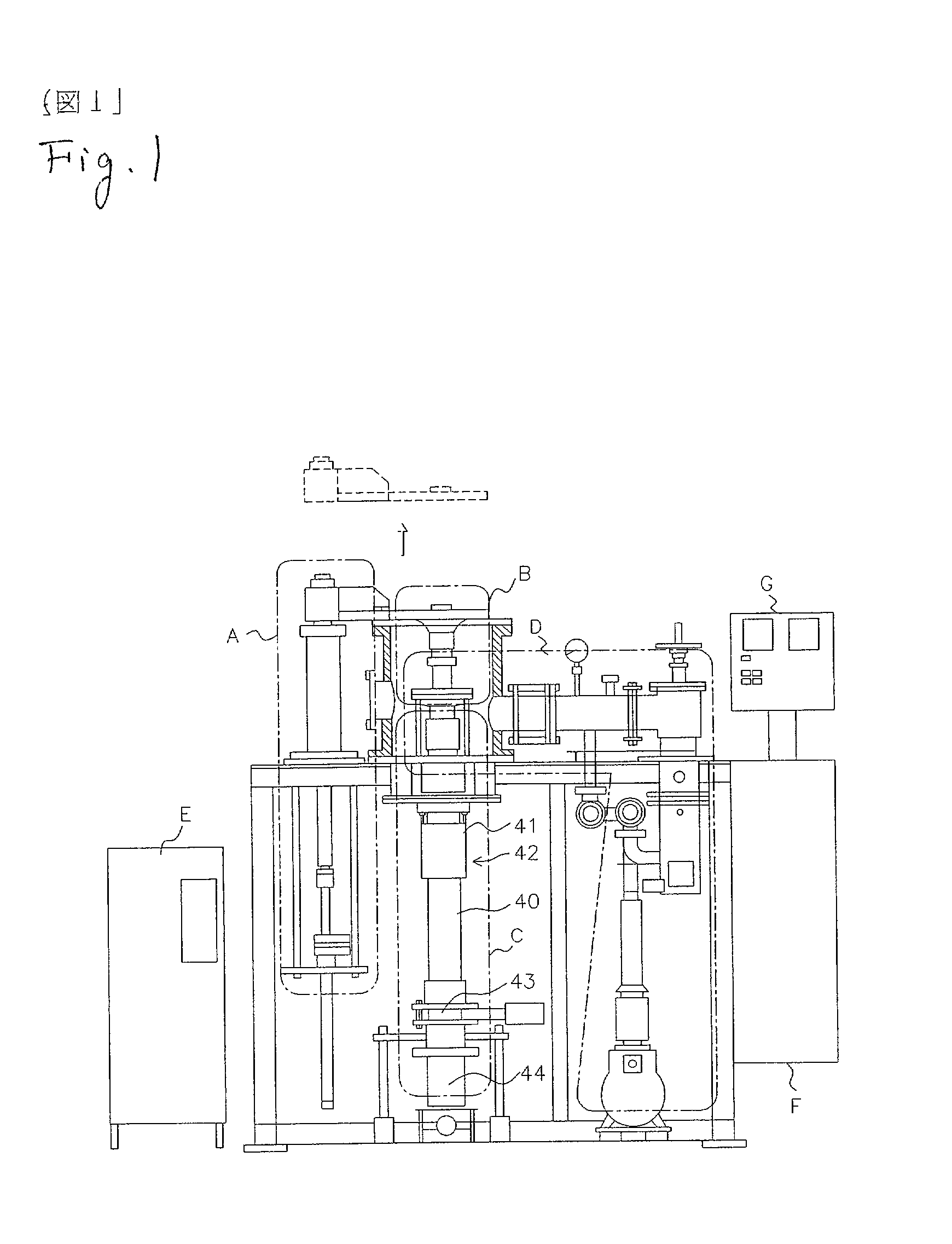
[0184] Thermoelectric semiconductor was produced using the production apparatus of monodisperse particle shown in FIG. 1.

[0185] A. Apparatus arrangement

[0186] In the production apparatus of monodisperse particle shown in FIG. 1, for piezoelectric actuator 12, laminar type piezoelectric element (NLA-5.times.5.times.18 made by Tokin Co.) was used. The capability is that the capacity is 1600 nF(.+-.20%), insulating resistance, 2.times.108.OMEGA.(.+-.50%), maximum displacement, 15.2 .mu.m / 100V(.+-.10%), maximum generating force, 85 kgf / 100V. This has slight hysteresis, but generally displace linearly. For diaphram 15, circular plate of stainless with diameter of 3 mm and thickness of 0.2 mm.

[0187] The above maximum displacement (15.2 .mu.m / 100V) is a value when the margin of this piezoelectric actuator is not constrained. However, in here, the piezoelectric actuator is fixed to the actuator press with adhesive, and further this actuator press is fixed to the inside of the holder block 3...

example 2

[0199] The production process according to the invention was carried out using Pb-63Sn, and the others were same as the example 1. In this case, the liquid level height in the scrucible 26 was 2.5 cm, the liquid back pressure, that is, the difference in pressure between inside and outside of the scrucible 26 was 0.03 kg / cm.sup.2, and then the monodisperse particle was produced. As a result, the monodisperse particles which were excellent in sphericity were obtained as the example 1 described above.

example 3

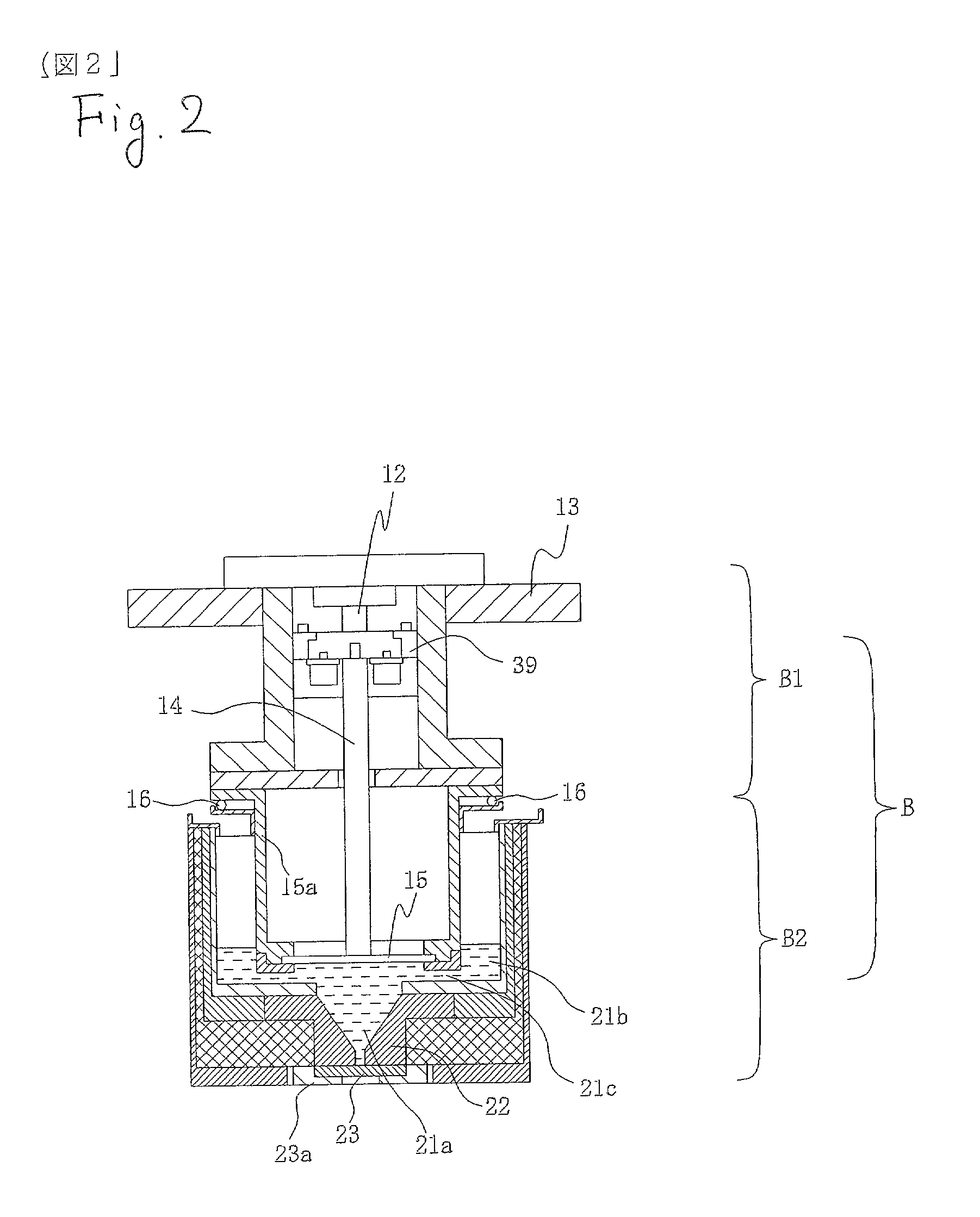
[0200] A. Apparatus arrangement

[0201] In the production apparatus of monodisperse particle, for piezoelectric actuator 12, laminar type piezoelectric element (NLA-5.times.5.times.18 made by Tokin Co.) was used. The capability is that the capacity is 1600 nF(.+-.20%), insulating resistance, 2.times.108.OMEGA.(.+-.50%), maximum displacement, 15.2 .mu.m / 100V(.+-.10%), maximum generating force, 85 kgf / 100V. This has slight hysteresis, but generally displaces linearly. For diaphram 15, circular plate of stainless with diameter of 3 mm and thickness of 0.2 mm was used.

[0202] The above maximum displacement (15.2 .mu.m / 100V) is a value when the margin of this piezoelectric actuator is not constrained. However, in here, the piezoelectric actuator is fixed to the actuator press with adhesive, and further this actuator press is fixed to the inside of the holder block 39. Thus, when the piezoelectric actuator is fixed to the apparatus in this way, the relation between applied voltage and displa...


PUM

PropertyMeasurementUnit
diameteraaaaaaaaaa
particle diameteraaaaaaaaaa
diameteraaaaaaaaaa

Abstract

It is the object to provide a production process of monodisperse particle in which monodisperse particle with uniform particle size (particle diameter) can be stably mass-produced, and monodisperse particle produced by this process, and its production apparatus. The supply pipe diameter deltaf is set to be greater than the orifice diameter deltao and the internal and external pressure of the slurry retention part b is controlled, and this allows to facilitate supply of the slurry through the supply pipe (21c), and continuously and efficiently supply the slurry, and then to produce monodisperse particle with uniform particle size (particle diameter).

Description

[0001] 1. Field of the Invention[0002] This invention relates to production process of monodisperse particle for producing monodisperse particle containing particles of substantially uniform particle size, and monodisperse particle, and further its apparatus.[0003] 2. Description of the Related Art[0004] Small particles, that is, small monodisperse particles are now increasing demand in various kinds of science and technology. For example, latex particle which is well known as small monodisperse particle, and produced by sol-gel process, has standard deviation of approximately 10% of average particle diameter in particle size (particle diameter) distribution, and is used as standard size particle in electron microscope observation. In semi-conductor industry, spherical soldering powder of uniform particle size (particle diameter) of 30 .mu.m to 40 .mu.m is required. Further, in HIP forming of alloy powder, spherical powder of uniform particle size (particle diameter) is required to ...

Claims


Application Information

Patent Timeline
Patent Type & Authority Applications(United States)
IPC IPC(8): B01J2/02B01J2/18B22F1/052B22F1/08B22F9/08
CPCB01J2/02B01J2/18B22F1/0014B22F9/08B22F2999/00B22F2202/01B22F1/052B22F1/08
Inventor KAWASAKI
Owner KAWASAKI CORP KK
Why Eureka
Try Eureka