Sensor apparatus and cantilever for it

a technology of cantilever and sensor, which is applied in the field of sensors, can solve the problems of limiting the applicability of cantilever, thermal actuation of cantilever, and requiring a relatively high heating power to excite cantilever at high frequencies, and achieves the effects of low power consumption, high sensitive chemical properties, and easy adaptability

a technology of cantilever and sensor, which is applied in the field of sensors, can solve the problems of limiting the applicability of cantilever, thermal actuation of cantilever, and requiring a relatively high heating power to excite cantilever at high frequencies, and achieves the effects of low power consumption, high sensitive chemical properties, and easy adaptability

US20020092359A1Inactive Publication Date: 2002-07-18SWISS FEDERAL INST OF TECH ZURICH

Image

  • Sensor apparatus and cantilever for it
  • Sensor apparatus and cantilever for it
  • Sensor apparatus and cantilever for it

Examples


Embodiment Construction

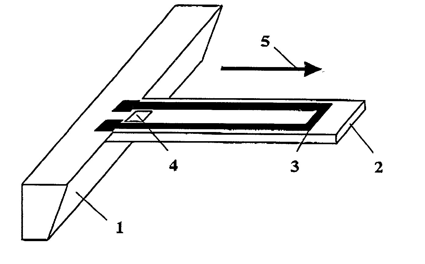
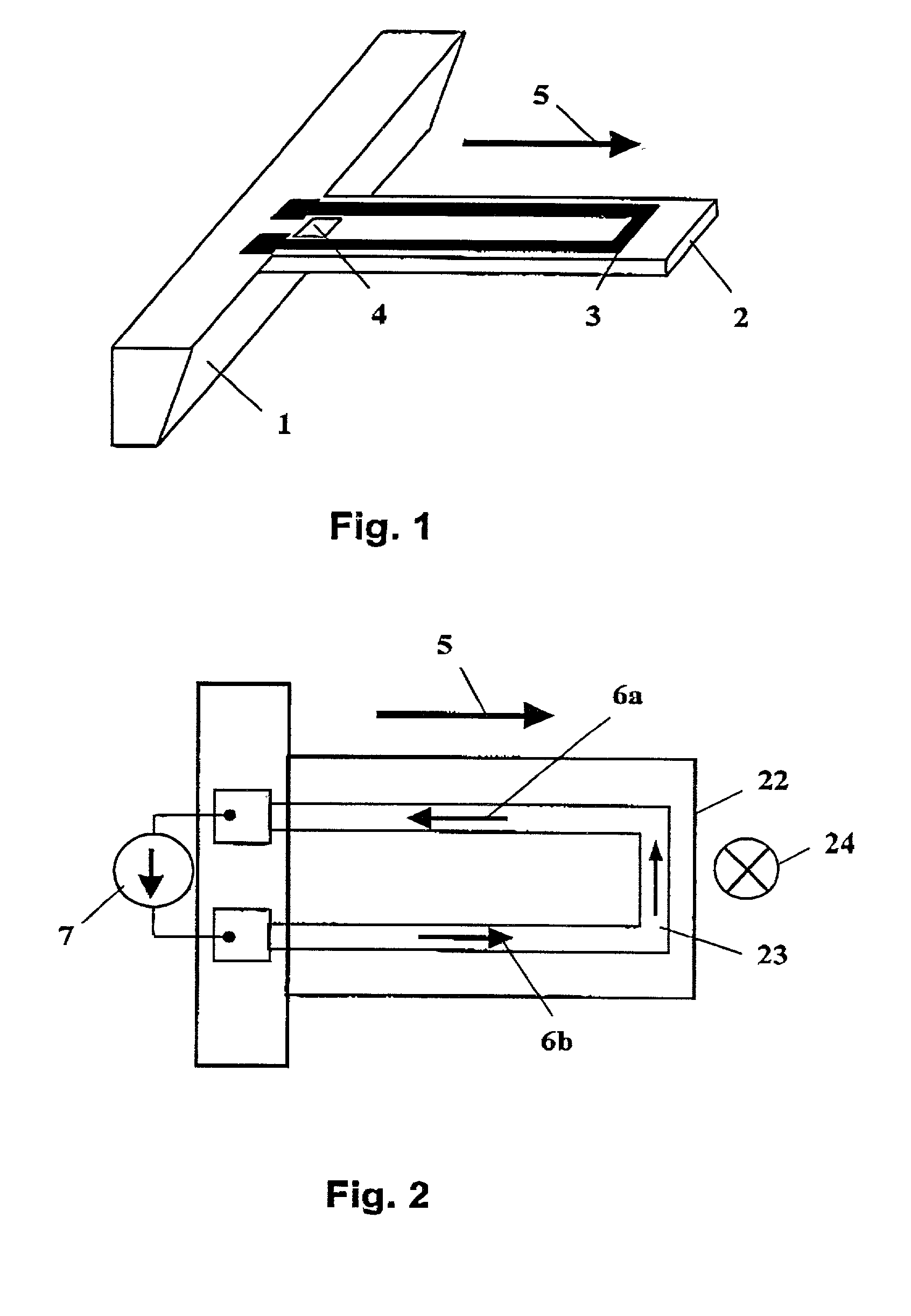
[0030] FIG. 1 shows a typical layout of a cantilever according to the invention in perspective. Cantilever 2 is at one end fixed to support base 1 which is part of the assembly, not shown in detail. Both, support base 1 and cantilever 2 are made from semiconductor material, e.g. silicon. Thus, a deflection sensor 4 can be directly integrated on the surface of cantilever 2, here located close to support base 1. Also on cantilever 2 is a conductor forming a current loop 3 in form of a U, usually made from metal or another conductive material. Arrow 5 indicates the direction of a static in-plane magnetic field. The source of this magnetic field is not shown; a conventional permanent magnet, direct-current (DC) coils, or the like may be used.

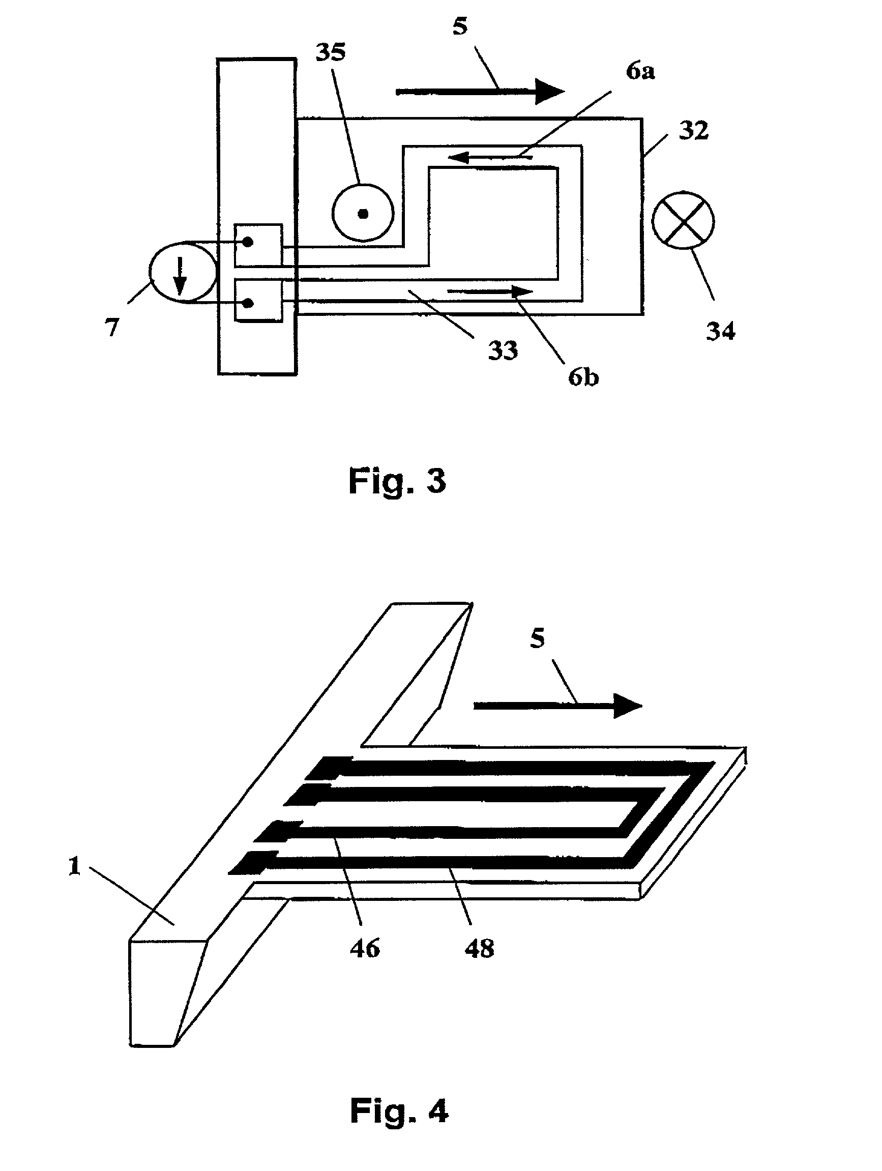
[0031] FIGS. 2 and 3 show two variations of a cantilever 22 and 32 with different conductor loop shapes. In operation a current, driven by current source 7 and indicated by arrows 6a and 6b in both figures, is applied to current loops 23 and 33, res...


PUM

PropertyMeasurementUnit
mechanical deflectionsaaaaaaaaaa
electrical currentaaaaaaaaaa
resonance frequencyaaaaaaaaaa

Abstract

A magnetically excited, resonant cantilever sensor apparatus has a cantilever as the transducer element. A static magnetic field is directed in the plane of the cantilever(s) cooperating with a current loop in / on the latter. Orienting the magnetic field along or perpendicular to the cantilever axis and controlling the current apprpriately allows for selective excitation of resonance or non-resonance modes and / or in a self-oscillation mode. The deflection of the cantilever is detected using piezoresistive or magnetic readout. The apparatus may be used as gas sensor, scanning force microscope, mechanical filter, temperature sensor or the like.

Description

[0001] 1. Field of the Invention[0002] The present invention relates to sensors, or more generally to apparatuses for exciting and detecting mechanical deflections and to the use of such apparatuses for mass-sensing, scanning probe microscopy, filtering electronic circuits, and similar applications. For such applications, cantilever structures and transducers of this structure are widely used because of their relative simplicity and robustness.[0003] 2. Related Art[0004] As mentioned, cantilever transducers have a number of applications as force sensors for scanning probe microscopes and as acceleration sensors; other applications include their use as chemical and biochemical sensors. An examples is shown in Thundat et al U.S. Pat. No. 5,719,324 "Microcantilever Sensor". Typically, cantilever devices employ piezoelectric films as one layer of the cantilever, but capacitive excitation has also been demonstrated, cf. S. Suzuki et al: "Semiconductor capacitance-type accelerometer with ...

Claims


Application Information

Patent Timeline
18 Jul 2002
Publication
US20020092359A1
IPC
G01G7/02; G01Q20/00; G01Q20/04; G01Q60/24
CPC
B82Y35/00; G01G7/02; G01Q20/04; G01Q10/045; Y10S977/873; Y10S977/865
Inventors
LANGE, DIRK; HAGLEITNER, CHRISTOPH