Dynamically compliant catheter

a catheter and dynamic technology, applied in the field of dynamically compliant catheters, can solve the problems of increased complications, undue large wound at the puncture site, and more time needed to stop bleeding, so as to minimize the hole at the entry site of the patien

Inactive Publication Date: 2002-07-18
WILSON ROBERT F +1
View PDF1 Cites 41 Cited by
  • Summary
  • Abstract
  • Description
  • Claims
  • Application Information

AI Technical Summary

Benefits of technology

0014] The backbone allows the catheter to retain a predetermined shape for ease of manipulation and placement of the catheter. The outer non-compliant, nonexpandable sheath limits the expansion of the catheter and is positioned at the insertion point into the patient. The adjustable sheath, however, expands. Thus, the catheter retains the narrow ins...

Problems solved by technology

Additionally, the larger the puncture hole, the greater the opportunity for complications and the more time needed to stop the bleeding after ...

Method used


Image

  • Dynamically compliant catheter
  • Dynamically compliant catheter
  • Dynamically compliant catheter

Examples


Embodiment Construction

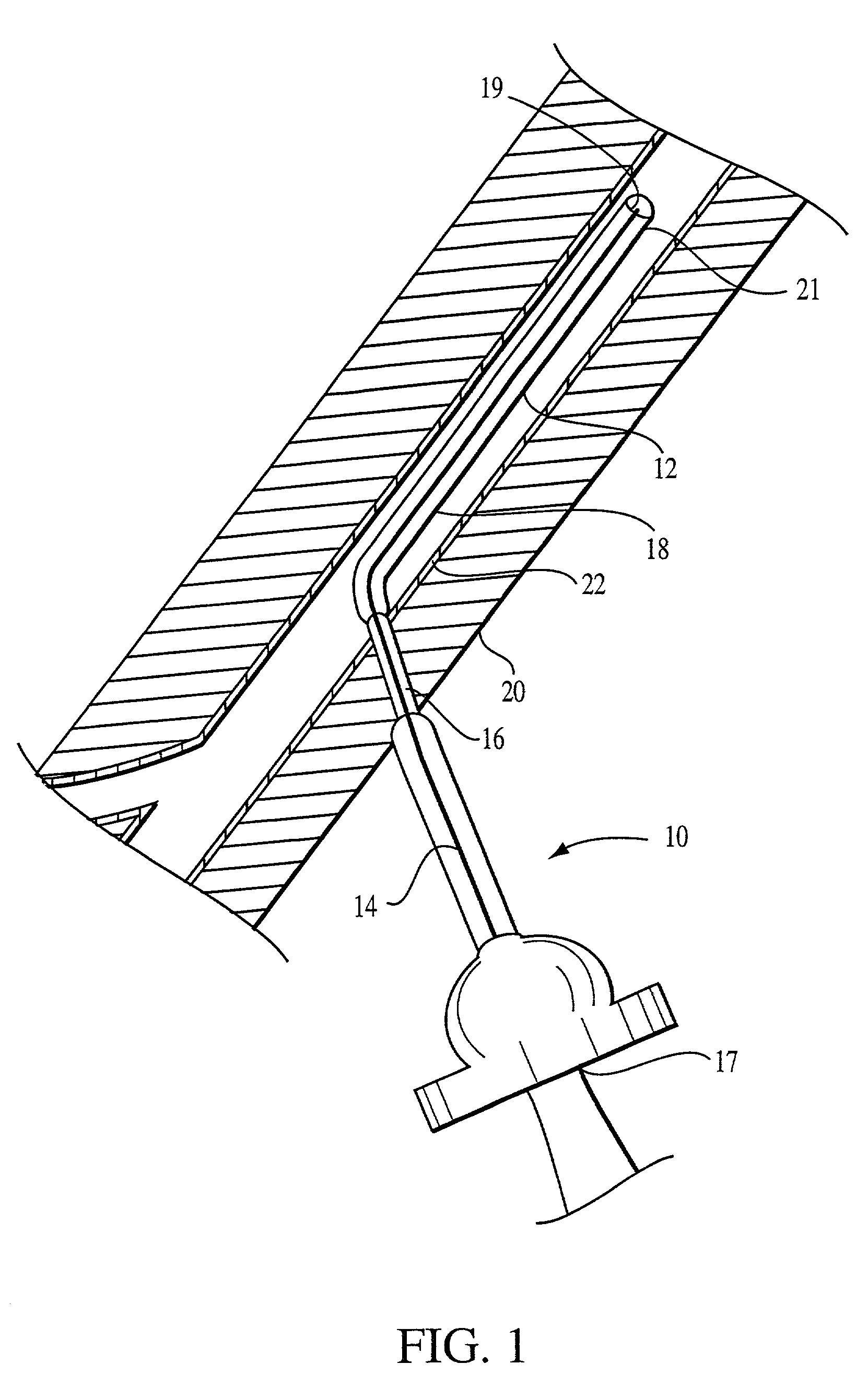
[0027] Referring to FIG. 1, a catheter 10 in one embodiment of the present invention is shown inserted into a patient to supply fluids, for example a contrast agent, to the blood stream. The catheter 10 is inserted into the patient through a puncture hole in the patient's skin 20 and in a blood vessel wall 22.

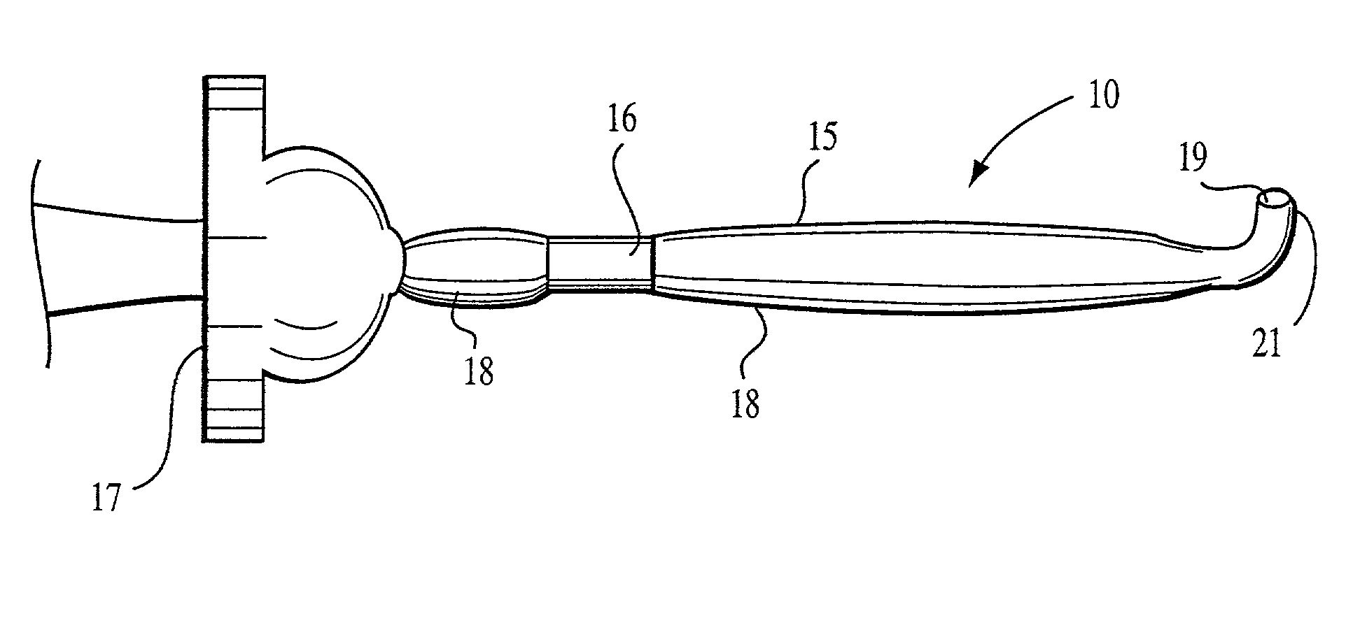
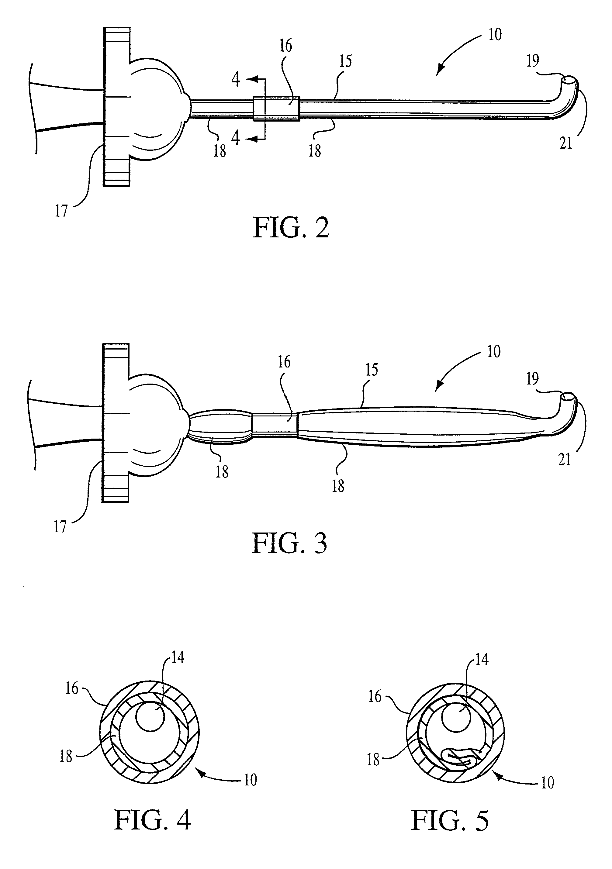
[0028] Referring to FIGS. 1, 2 and 3, the catheter 10 has a hollow elongate body 12 that extends from the patient's exterior and terminates inside the blood vessel. The distal end 21 of the catheter 10 is the end inserted into the patient whereas the proximal end of the catheter 10 is the end closest to the user (usually a physician or clinician).

[0029] Located internally in the catheter 10 is a backbone 14, which serves to shape the catheter 10. The backbone 14 is shown as an interior structure of the catheter 10 and is encompassed by the conduit 15 of the catheter 10, which conduit is the outermost portion of the catheter 10. The backbone 14 further provides strength, structu...


PUM


Abstract

A catheter enabling a reduced puncture hole size into the skin and blood vessel is disclosed. In one embodiment, the catheter has an elongate body having an expandable sheath extending at least a portion of its length. A pressure constraining sheath is positioned to surround the expandable sheath, at a selected region to prevent expansion of the inner sheath at the region of the constraining sheath. In one preferred use, the constraining sheath is positioned at the puncture hole. During use, the catheter increases in cross-section by an expandable sheath expanding from a first diameter to a second diameter. However, the outer sheath does not expand, maintaining a small diameter at the puncture site.

Description

[0001] This invention relates generally to angiography and / or particularly to an improved catheter for injecting medical fluids such as radiographic contrast fluid into living organisms.[0002] Angiography is a procedure used in the treatment of cardiovascular conditions including abnormalities or restrictions in blood vessels of a human or animal body. During angiography, a radiographic contrast material is injected through a catheter into a vein or artery, which then passes to vascular structures in fluid communication with the vein or artery. When X-rays are passed through the region of the body into which the contrast material is injected, they are absorbed by the contrast material, providing radiographic images of the desired vascular structure(s). The images can be recorded on film or video tape and / or displayed on a fluoroscope monitor. The images can be used for many purposes, as for example diagnostics, and for operative procedures such as angioplasty, wherein a balloon is i...

Claims


Application Information

Patent Timeline
IPC IPC(8): A61M25/00
CPCA61M25/0023
Inventor WILSON, ROBERT F.DUCHON, DOUGLAS J.
Owner WILSON ROBERT F
Why Eureka
Try Eureka