Magnetically powered reciprocating engine

Inactive Publication Date: 2002-09-05
SULLIVAN MARK L
View PDF0 Cites 38 Cited by
  • Summary
  • Abstract
  • Description
  • Claims
  • Application Information

AI Technical Summary

Problems solved by technology

Thus, the government has a deep interest in both the cost and environmental benefits of an alternatively fueled e

Method used


Image

  • Magnetically powered reciprocating engine
  • Magnetically powered reciprocating engine
  • Magnetically powered reciprocating engine

Examples


Example

[0026] The typical gasoline powered engine receives its power from the chemical energy in a gasoline and air mixture. The gasoline is vaporized in a carburetor. Within the carburetor, air is sucked into an air filter and then around a tube filled with gas pumped from the gas tank. The air rushes past the tube, and it carries along some gas vapor, and the mixture goes to one of the cylinders. Cylinders are large tubes sealed at one end and blocked at the other by a movable plug called a piston. As the piston moves down, it sucks in the gas / air mixture from the carburetor through a pipe called the intake manifold. When the piston reaches the bottom of its stroke, the inlet valve closes, and the piston moves back up the cylinder, compressing the gas / air mixture to rest in one-sixth of its original volume. This is generally known as the compression ratio.

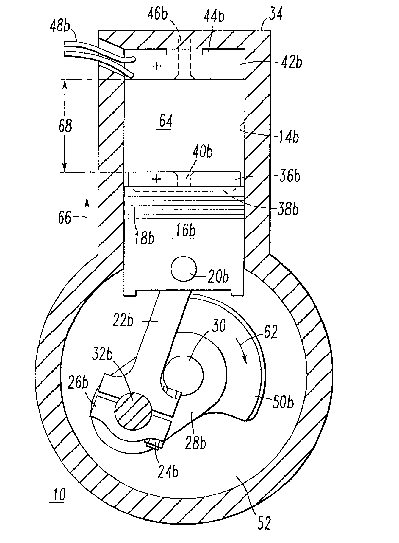
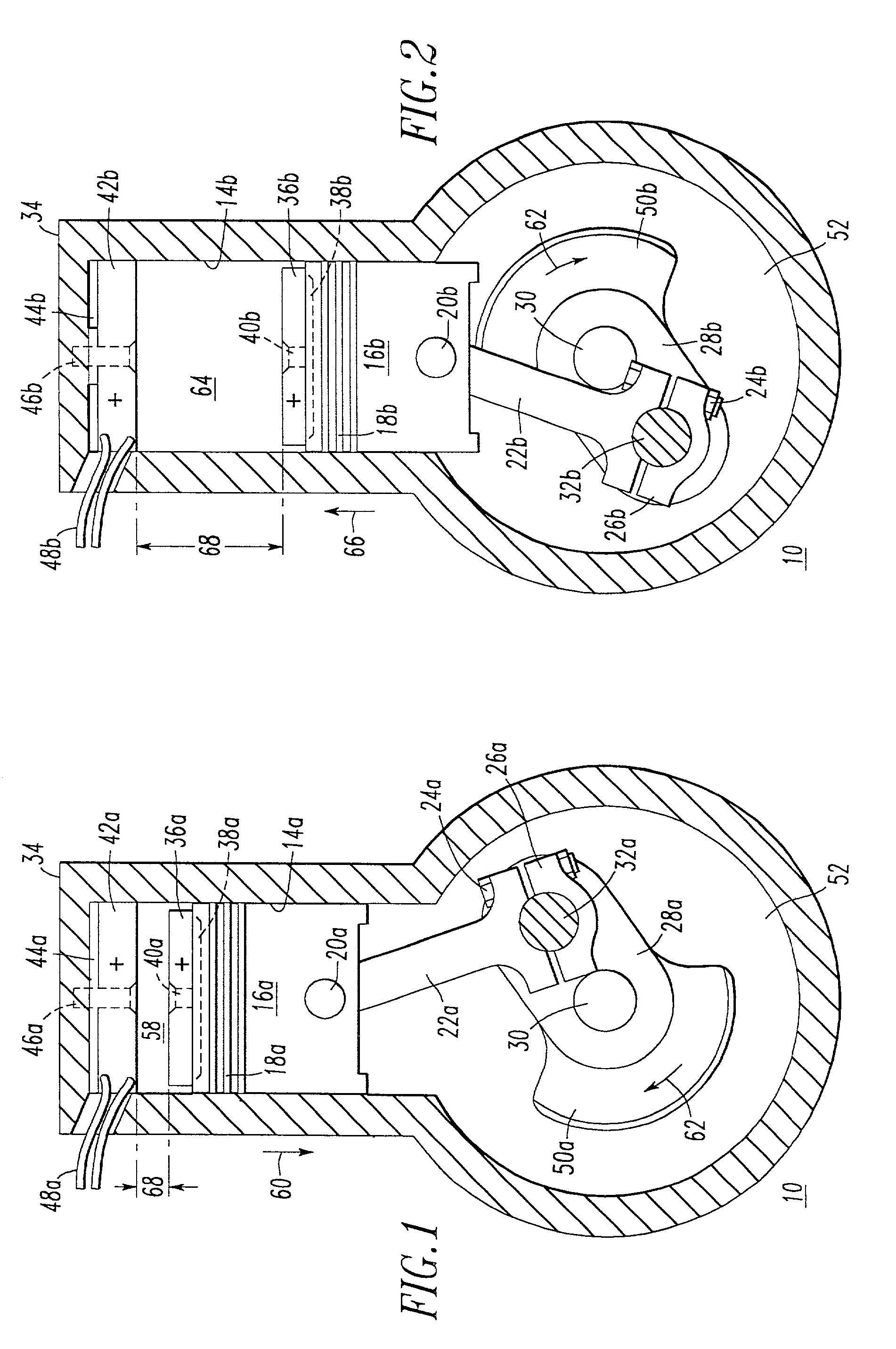
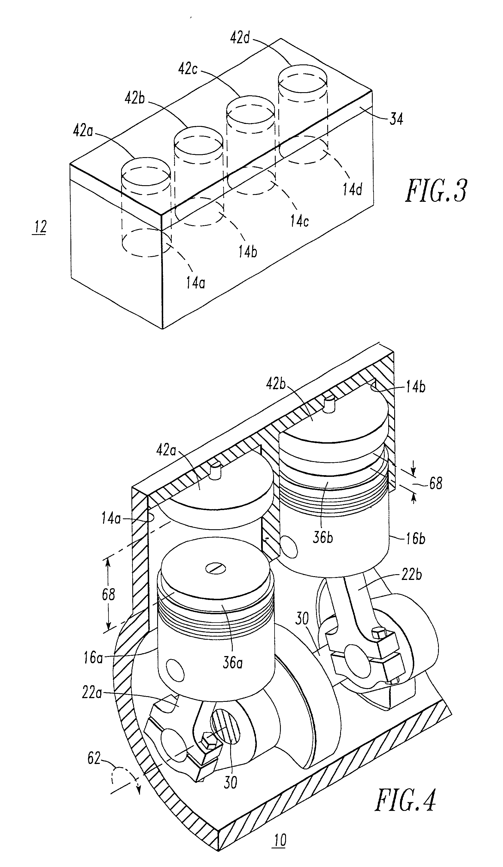
[0027] Now referring to FIG. 1 of the present invention, there is shown a magnetically powered engine 10 having a cylinder 14a, a pist...


PUM


Abstract

A magnetically powered engine adaptable to and modifiable to any gasoline-powered automobile, truck, motorcycle, bus, marine and other small engines having an engine block containing at least one cylinder, at least one piston, a crankcase, and at least one connecting rod secured to a lower portion of said piston and pivotally to a crankshaft enclosed in said crankcase. An electrical power source provides electrical current to an electromagnet fastened within a head of a cylinder, whereby said electromagnet is opposed to a permanent magnet having a fixed charge and secured to an upper surface of a piston for creating a magnetic field between the electromagnet and the permanent magnet causing a magnetic force driving the piston away from the electromagnet and reciprocating to cause a repulsive magnetic force between an adjacent electromagnet and permanent magnet, thus, transferring this reciprocating motion to a crankshaft and ultimately to a driveshaft in any powered vehicle, including automobiles, trucks, motorcycles, buses, and small engines, and likewise, adaptable to marine engines for driving a shaft which turns a propellor apparatus. The magnetically powered engine is also adaptable to smaller engines, including lawn mowers, small tractors, weedeaters and other similar gasoline-powered motors. Adaptation to the magnetically powered engine eliminates many components of a typical gasoline-powered engine including gasoline tanks, fuel lines, fuel pumps, tail pipes, mufflers, carburetors, etc.

Description

[0001] 1. Field of the Invention[0002] This invention relates generally to a magnetically powered reciprocating engine especially adaptable to and modifiable to any gasoline powered automobile, truck, marine or other small engines.[0003] 2. Description of the Prior Art[0004] The gasoline powered engine has been a major factor in American industry and manufacturing, as well as abroad. Technologies have produced hybrid electric and fuel cell vehicles which offer the prospect of significant emissions reductions for both toxic pollutants and greenhouse gases. Government policies and incentives now encourage an alternative to the gasoline engine. Thus, the government has a deep interest in both the cost and environmental benefits of an alternatively fueled engine due to the fact that road transport is one of the major sources of air pollution, especially in urban areas.[0005] One attempt at a self-timing piston electric engine is disclosed in U.S. Pat. No. 2,296,554 issued to A. K. Hinch...

Claims


Application Information

Patent Timeline
IPC IPC(8): F02B75/16F02B75/18H02K37/10H02K53/00
CPCF02B75/16F02B2075/1808F02B2075/1812F02B2075/1816F02B2075/1824F02B2075/1832F02B2075/184H02K37/10H02K53/00
Inventor SULLIVAN, MARK L.
Owner SULLIVAN MARK L
Why Eureka
Try Eureka