Baseband signal converter for a wideband impulse radio receiver

a radio receiver and baseband signal technology, applied in the field of radio receivers, can solve the problems of low reliability, low average power, and low reliability of conventional narrow band am, fm, cdma, tdma and similar wireless communication methods and systems, and achieve the effects of improving reliability, reducing power consumption, and improving reliability

Inactive Publication Date: 2002-09-12
ALEREON
View PDF29 Cites 85 Cited by
  • Summary
  • Abstract
  • Description
  • Claims
  • Application Information

AI Technical Summary

Benefits of technology

0026] Each converter circuit in the device includes an integrator circuit coupled to the RF signal input and a pulse generator coupled to the timing pulse input. The pulse generator provides a sampling pulse to the integrator to control the period during which the integrator integrates each pulse in the RF input signal. The output of the integrator is coupled through a buffer a...

Problems solved by technology

Conventional narrow band AM, FM, CDMA, TDMA and similar wireless communications methods and systems have not fully met these needs.
Because impulse radio signals are divided in time rather than in frequency, time related effects, such as multipath interference, can be separated, resulting in lower average power and higher reliability for a given power level.
If a radar system used a pulse of equivalent bandwidth at a higher carrier frequency, the material penetration properties would usually be impaired.
Existing IR receivers typically use mixer or sampling technology which is large in size, inefficient in power consumption and which is difficult to reproduce in a manufacturing environment.
This results in a high cost to the user.
However, in a real world environment, a perfect Gaussian pulse is not achievable.
In a system that does not use a coding component, differentiating between separate transmitters would be difficult.
If there were a large number of impulse radio users within a confined area, there...

Method used


Image

  • Baseband signal converter for a wideband impulse radio receiver
  • Baseband signal converter for a wideband impulse radio receiver
  • Baseband signal converter for a wideband impulse radio receiver

Examples


Embodiment Construction

[0036] Baseband Converter Device Overview

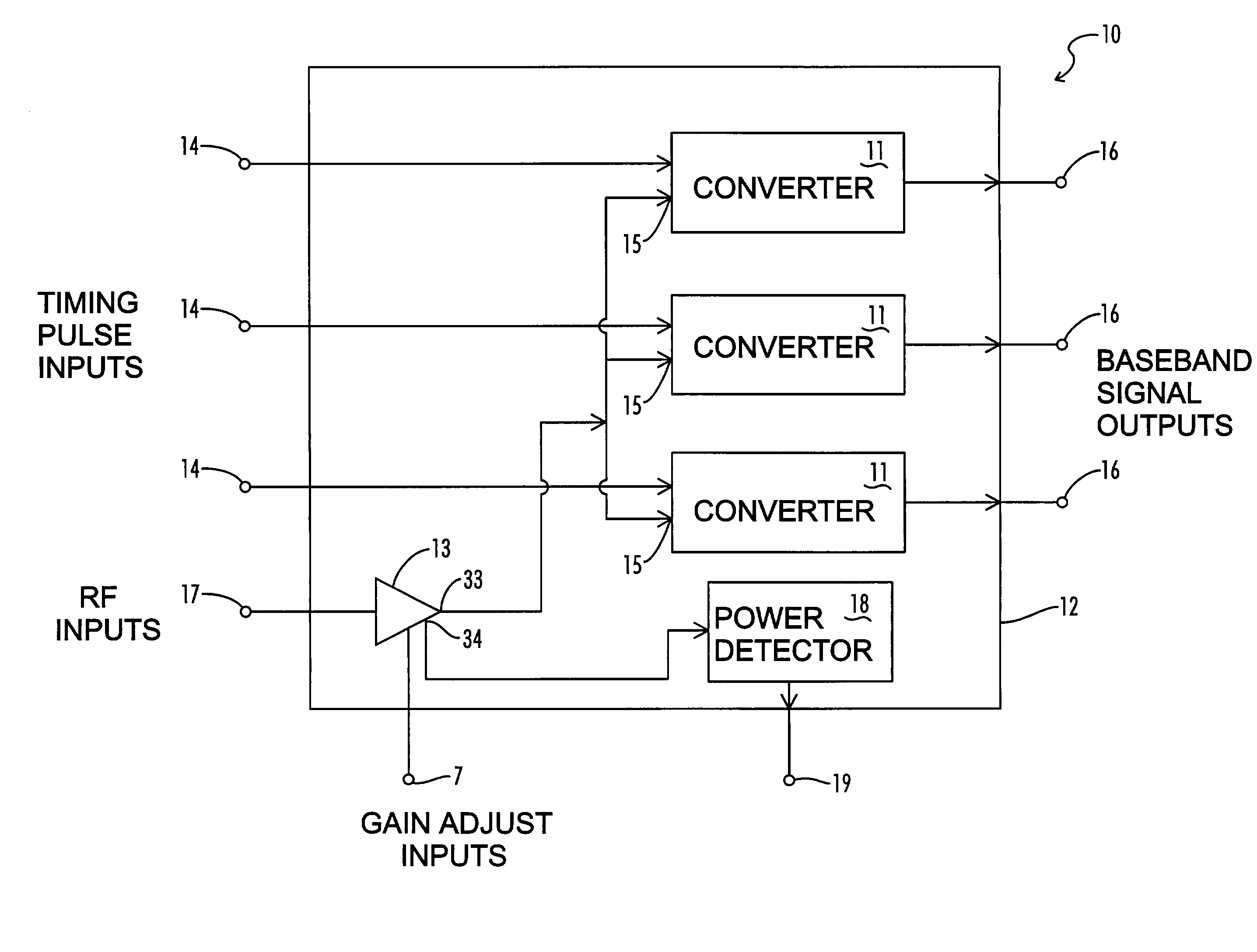
[0037] A block diagram of one embodiment of the baseband converter device 10 of the present invention is shown in FIG. 1. Preferably, the converter device 10 is manufactured as an application specific integrated circuit (ASIC) in which the various device circuits are fabricated within a single integrated circuit device package 12. In the embodiment of FIG. 1, the device 10 includes three separate baseband converter circuits 11. Each converter circuit 11 has an RF signal input 15, a timing pulse input 14, and a baseband signal output 16. The RF signal inputs 15 for each converter circuit 11 are internally connected in parallel to the output 33 of a broadband, variable gain RF amplifier 13. The input of amplifier 13 is connected to device RF input 17 external to the device package 12 so that the device RF input 17 can be electrically coupled to an antenna 56 as part of an impulse radio receiver 100 (FIG. 7). Similarly, each timing pulse input 1...


PUM


Abstract

A baseband signal converter device for an impulse radio receiver combines multiple converter circuits and an RF amplifier in a single integrated circuit package. Each converter circuit includes an integrator circuit that integrates a portion of each RF pulse during a sampling period triggered by a timing pulse generator. The integrator capacitor is isolated by a pair of Schottky diodes connected to a pair of load resistors. A current equalizer circuit equalizes the current flowing through the load resistors when the integrator is not sampling. Current steering logic transfers load current between the diodes and a constant bias circuit depending on whether a sampling pulse is present.

Description

[0001] This application claims benefit of co-pending U.S. application Ser. No. 09 / 356,384 filed Jul. 16, 1999, entitled "Baseband Signal Converter for a Wideband Impulse Radio Receiver", the disclosure of which is hereby incorporated by reference.BACKGROUND OF THE INVENTION[0002] The present invention relates generally to radio receivers adapted to receive and process wideband impulse radio signals. More particularly, this invention pertains to devices and circuits for accurately converting in an impulse radio receiver a series of time-modulated radio pulses into a baseband signal.[0003] There is a continuing need for the development of advanced wireless devices for communications of voice and data, for materials measurement, navigation, environmental sensing, radar, security and numerous other civilian and military applications of radio technology. Improvements are needed in the underlying technology to provide greater reliability, greater accuracy, lower power consumption, lower c...

Claims


Application Information

Patent Timeline
IPC IPC(8): H04B1/7163H04B1/7183H04B1/719H04L25/49
CPCH04B1/71637H04B1/7183H04B1/719H04L25/4902
Inventor JETT, PRESTONLARSON, LAWRENCE E.POLLACK, BRET A.ROWE, DAVID A.
Owner ALEREON
Why Eureka
Try Eureka