Optical fiber cable for use in harsh environments

a fiber optic cable and harsh environment technology, applied in the field can solve the problems of optical fiber loss resistance to hydrogen, optical performance of optical fiber, and high design requirements of fiber optic cables, and achieve the effects of low hydrogen permeability, low cost, and low cos

Inactive Publication Date: 2002-09-12
WEATHERFORD TECH HLDG LLC
View PDF0 Cites 26 Cited by
  • Summary
  • Abstract
  • Description
  • Claims
  • Application Information

AI Technical Summary

Benefits of technology

[0007] A further object of the invention is to provide such a fiber optic cable that minimizes the exposure of optical fibers to hydrogen contained in the harsh environment, particularly at high temperatures.
[0008] A still further object of the invention is to provide such a fiber optic cable wherein the optical fibers contained in the cable are not exposed to significant damaging strain over a wide range of operating temperatures.
[0009] According to the present invention, a fiber optic cable includes a core and a surrounding protective layer. The core includes an inner tube having one or more optical fibers contained therein, and the surrounding protective layer includes an outer tube received over the inner tube, and a layer of buffer material positioned between the outer tube and the inner tube, the buffer material maintaining the inner tube generally centrally located within the outer tube and providing a mechanical link between the inner tube and the outer tube to prevent relative movement therebetween.
[0010] According further to the present invention, the inner tube may be coated with a low hydrogen permeability material to minimize the entrance of hydrogen into the inner tube. According still further to the invention, the low hydrogen permeability material may be coated with a protective layer of hard, scratch resistant material to protect the integrity of the low hydrogen permeability material.
[0011] In still further accord with the invention, the area in the inner tube may be filled with a filler material, the filler material being selected to have a sufficient viscosity to resist the shear forces applied to it as a result of the weight of the optical fibers within the tube while allowing movement of the optical fibers within the tube during spooling, deployment and handling of the cable to thereby prevent damage and microbending of the optical fibers. According still further to the present invention, the filling material may be impregnated with a hydrogen absorbing / scavenging material.
[0013] The fiber optic cable of the present invention provides a significant advantage over the prior art. The cable provides significant resistant to the damaging effects of hydrogen on an optical fiber by minimizing the exposure of the optical fibers to hydrogen. The inner tube of the cable is coated with a low hydrogen permeability material to limit the ingress of hydrogen into the inner tube. Additionally, the filling material within the inner tube is impregnated with a hydrogen absorbing / scavenging material to remove any hydrogen that may enter the inner tube. A protective coating is received over the low hydrogen permeability material to maintain the integrity of the coating for handing and manufacturing of the cable. To provide a high strength cable capable of deployment in a harsh environment, the inner tube is surrounded by protective layer that includes a buffer material surrounded by an outer tube.

Problems solved by technology

For example, the harsh environment encountered in down-hole fiber optic sensing applications places demanding requirements on the design of fiber optical cables for use in the down-hole environment.
The deleterious effects of hydrogen on the optical performance of optical fiber, particularly in sub-sea installations for the telecommunications industry, have long been documented.
However, at the elevated temperatures experienced in a harsh down-hole environment, such coatings lose their resistance to permeability by hydrogen.

Method used


Image

  • Optical fiber cable for use in harsh environments
  • Optical fiber cable for use in harsh environments
  • Optical fiber cable for use in harsh environments

Examples


Embodiment Construction

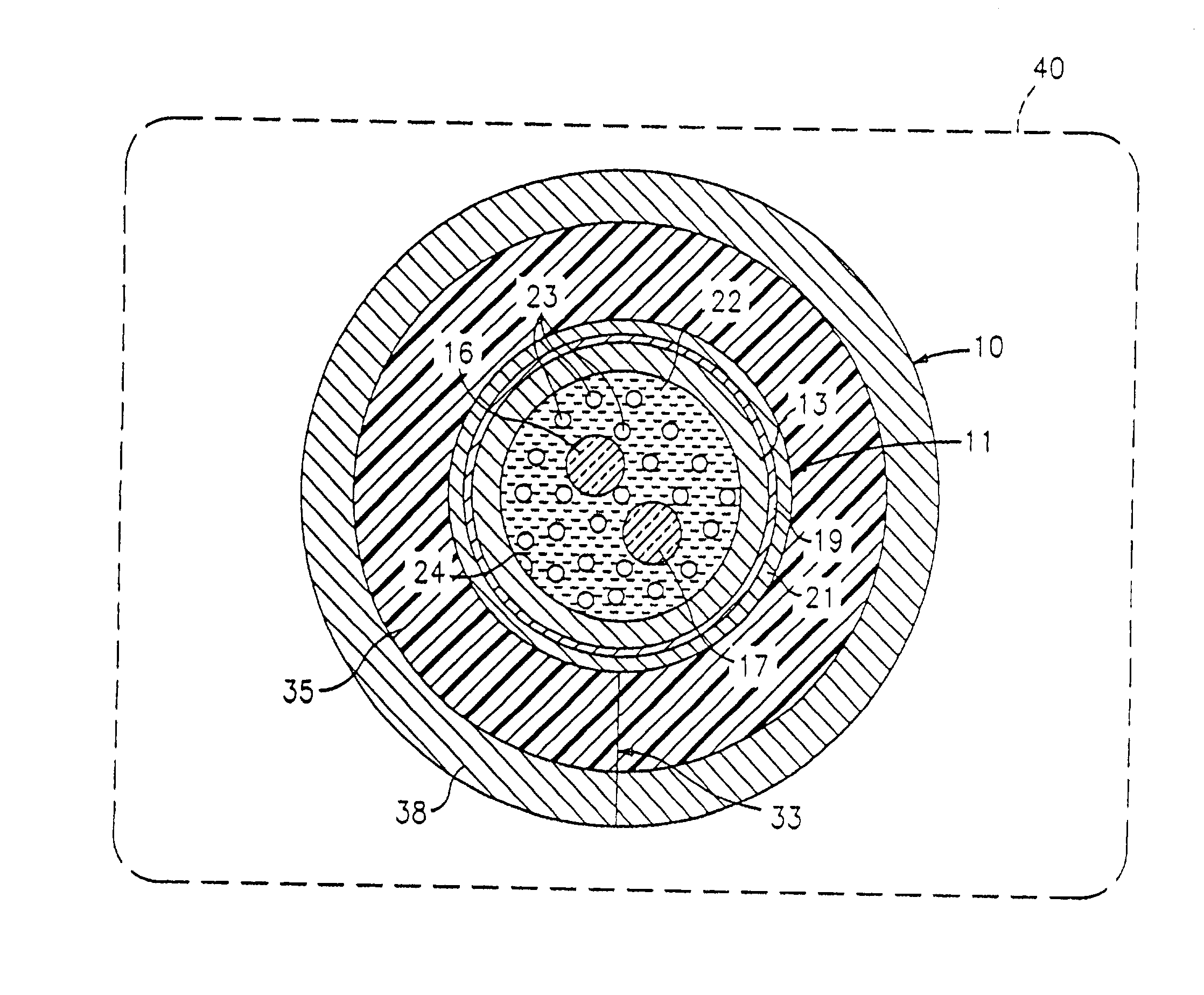
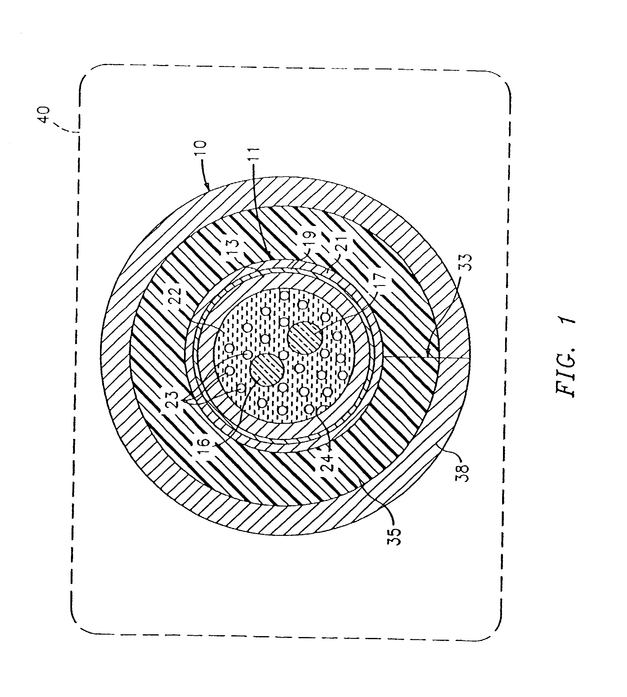
[0017] Referring now to FIG. 1, a fiber optic cable 10 manufactured in accordance with the present invention includes a fiber in metal tube (FIMT) core II having an inner tube 13 surrounding one or more optical fibers 16, 17. The inner tube 13 may be a laser welded tube, e.g., a length-wise laser welded tube, manufacture from a corrosion resistant material, such as a corrosion resistant metal alloy. Examples of suitable corrosion resistant metal alloys include, but are not limited to; Stainless Steel 304; Stainless Steel 316; Inconel 625; Incoloy 825. The inner tube 13 diameter may be in the range of 1.1 to 2.6 mm, and in an exemplary embodiment of the invention is 2.4 mm. Although the inner tube is described as being 1.1 to 2.6 mm in diameter, the diameter of the inner tube may vary over a large range, depending upon the materials used and the number of optical fibers to be placed in the inner tube. The inner tube 13 wall thickness is selected to be sufficient for the laser welding...


PUM


Abstract

A fiber optic cable includes a core and a surrounding protective layer. The core includes an inner tube having one or more optical fibers contained therein, and the surrounding protective layer includes an outer tube received over the inner tube, and a layer of buffer material positioned between the outer tube and the inner tube. The buffer material maintains the inner tube generally centrally located within the outer tube and providing a mechanical link between the inner tube and the outer tube to prevent relative movement therebetween. The inner tube may be coated with a low hydrogen permeability material to minimize the entrance of hydrogen into the inner tube. The low hydrogen permeability material may be coated with a protective layer of hard, scratch resistant material to protect the integrity of the low hydrogen permeability material. The area in the inner tube not occupied by the optical fibers may be filled with a filler material, the filler material being selected to have a sufficient viscosity to resist the shear forces applied to it as a result of the weight of the optical fibers within the tube while allowing movement of the optical fibers within the tube during spooling, deployment and handling of the cable to thereby prevent damage and microbending of the optical fibers. The filling material may be impregnated with a hydrogen absorbing / scavenging material to remove any excess hydrogen within the inner tube. The optical fibers have an excess length with respect to the inner tube, and the cable may include an outer jacket of a high temperature, protective material to protect the cable during handling and installation.

Description

TECHNICAL FIELD[0001] The present invention relates to fiber optic cables, and more particularly, to fiber optic cables for use in harsh environmentsBACKGROUND OF INVENTION[0002] With advancements in the area of fiber optic sensors, particularly for use in harsh environments, such as in oil and gas wells, there is an increasing need for fiber optic cables that can survive harsh environments. For example, the harsh environment encountered in down-hole fiber optic sensing applications places demanding requirements on the design of fiber optical cables for use in the down-hole environment. Such a fiber optic cable may be used to interconnect a down-hole fiber optic sensor with instrumentation located at the surface of a well bore.[0003] Down-hole environmental conditions can include temperatures in excess of 130.degree. C., hydrostatic pressures in excess of 1000 bar, vibration, corrosive chemistry and the presence of high partial pressures of hydrogen. Down-hole applications also lead...

Claims


Application Information

Patent Timeline
Patent Type & Authority Applications(United States)
IPC IPC(8): E21B17/00E21B47/12G02B6/44
CPCE21B17/00E21B47/123G02B6/4427G02B6/4484G02B6/4488G02B6/4492E21B47/135G02B6/44382
Inventor BONJA, JEFFREY A.NORTON, DOUGLAS A.CHESTNUT, CHRISTOPHER J.RUBINO, ROBERT A.
Owner WEATHERFORD TECH HLDG LLC
Why Eureka
Try Eureka