Compact direct methanol fuel cell

a fuel cell, compact technology, applied in the direction of fuel cell details, cell components, electrochemical generators, etc., can solve the problems of large hydrogen storage tank, difficult handling, and inability to meet the requirement of miniature siz

Inactive Publication Date: 2002-09-12
CAO YIDING +1
View PDF2 Cites 54 Cited by
  • Summary
  • Abstract
  • Description
  • Claims
  • Application Information

AI Technical Summary

Benefits of technology

0010] It is an objective of the present invention to provide a compact, lightweight direct methanol fuel cell unit that eliminates the need for an air compressor or a fuel pump. The fuel cell unit comprises a circular membrane electrode assembly (MEA), an annular fuel reservoir, a circular air flow duct, and a CO.sub.2 relief valve. The MEA includes a cathode, a proton excha

Problems solved by technology

Since compressed hydrogen is at an extremely high pressure, it is very difficult to handle.
In addition, a large hydrogen storage tank is needed, which could not satisfy the requirement of miniature size.
While the inventors recognize many technological advancements recently described by prior arts, the current existing direct-methanol fuel cell technology cannot satisfy many of the key technical requirements for a portable system having a small size and weight due to several major factors.
The inclusion of

Method used


Image

  • Compact direct methanol fuel cell
  • Compact direct methanol fuel cell
  • Compact direct methanol fuel cell

Examples


Embodiment Construction

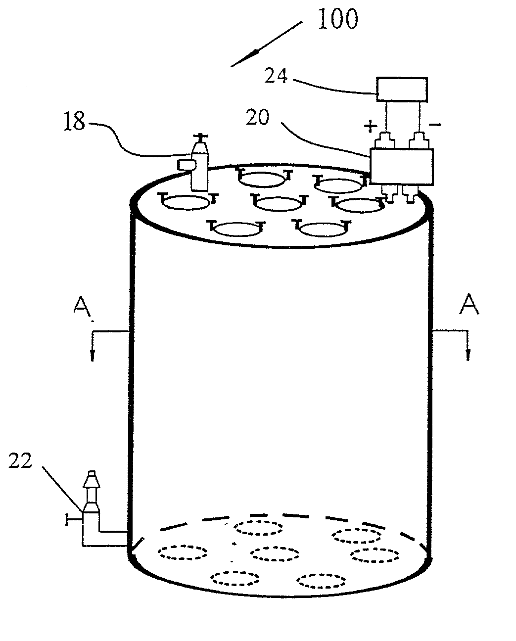
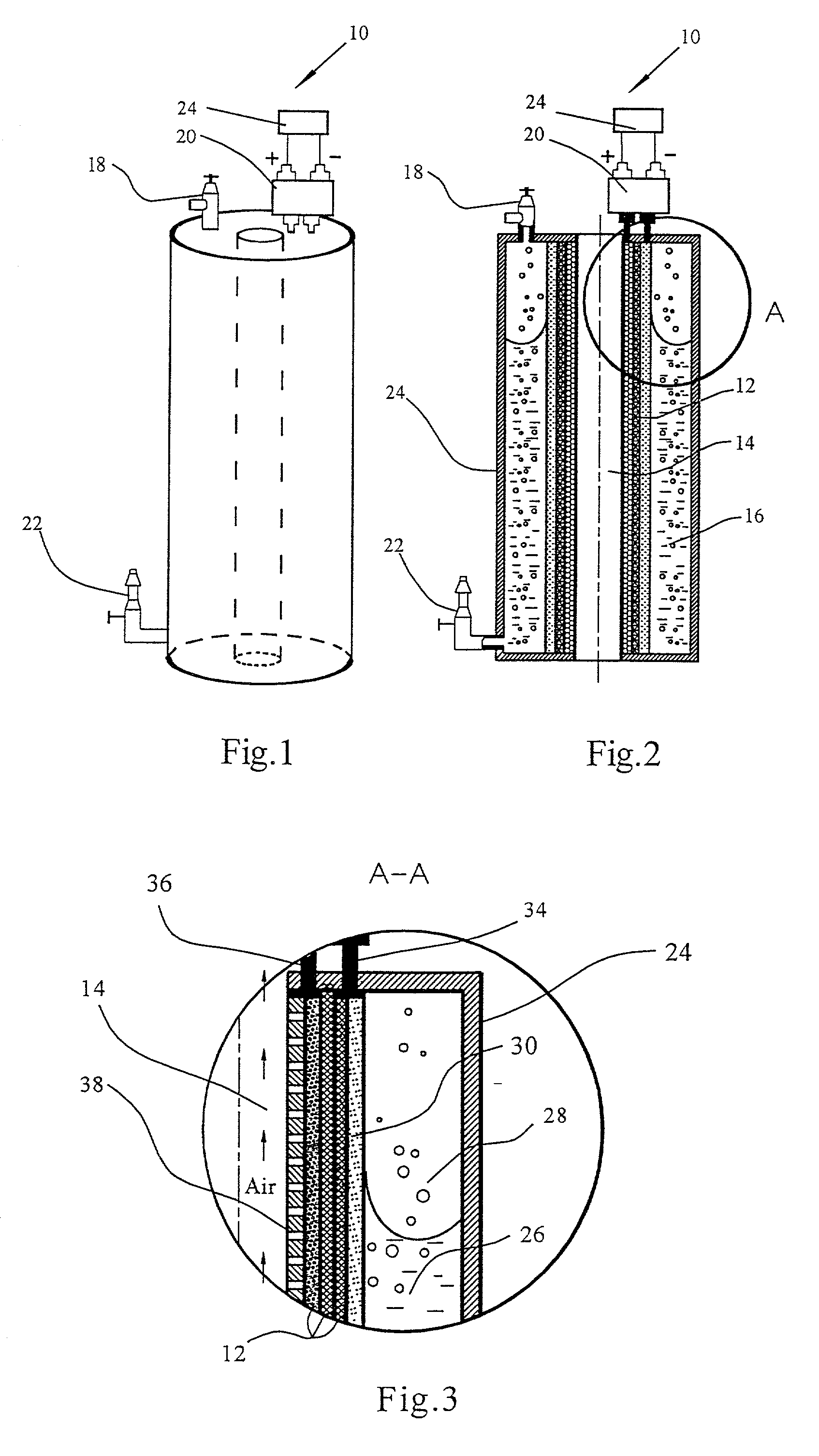
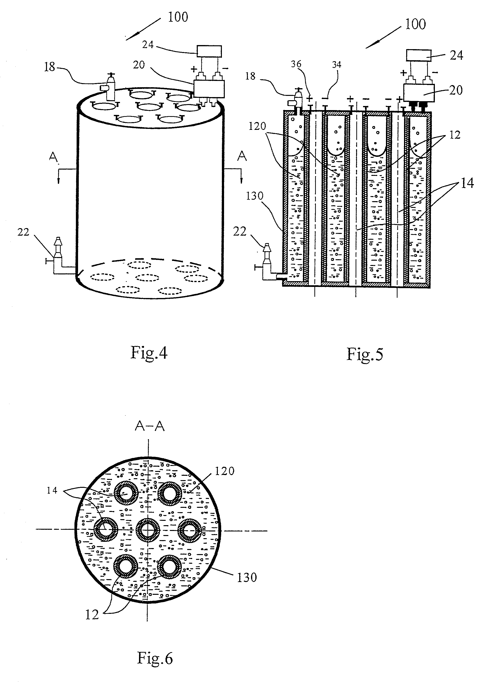
[0019] FIG. 1 shows a direct methanol fuel cell unit 10 according to a preferred form of the present invention, FIG. 2 is a-vertical cross-sectional illustration of the fuel cell unit 10, and FIG. 3 is an enlarged view of the interior structure of the fuel cell unit 10. With reference to FIG. 2, the fuel cell unit 10 generally comprises a circular membrane electrode assembly (MEA) 12 having a cathode, a proton exchange membrane (PEM), and an anode, a circular air flow duct 14 on the cathode side of the MEA 12, an annular fuel reservoir 16 on the anode side of the MEA 12 with a CO.sub.2 release mechanism, a CO.sub.2 relief valve 18, and a control unit 20. Initially, an amount of water / methanol mixture is filled within the annular reservoir as the fuel. Turning now to FIG. 3, there is provided an enlarged view of the interior structure of the fuel cell unit 10. A porous layer 30 with interconnected pores and an appropriate thickness and pore size is provided at the inner surface of th...


PUM


Abstract

A compact, lightweight direct methanol fuel cell unit includes a circular membrane electrode assembly (MEA) having a cathode, a proton exchange membrane (PEM), and an anode, an air flow duct on the cathode side of the MEA, an annular fuel reservoir on the anode side of the MEA which contains a mixture of methanol and water as fuel, a carbon dioxide (CO.sub.2) relief valve communicating with the fuel reservoir, and a control unit. Due to the CO.sub.2 release mechanism, the fuel cell is completely self-sustaining without the need for a mechanical auxiliary system. Additionally, the control unit improves the stability of the fuel cell power output and the catalysis activity of the MEA. Another embodiment of the present invention is a direct methanol fuel cell system which incorporates a number of MEAs and a fuel cell reservoir. All the cathodic electrical terminals of the MEAs are serially connected together while they are electronically communicating with the control unit. The anodic electrical terminals similarly communicate electronically with the control unit. Higher power and voltage are thus attained while maintaining a compact size of the fuel cell system.

Description

CROSS REFERENCES TO RELATED APPLICATIONS[0001] This application is a continuation of provisional application No. 60 / 271,491 filed Feb. 27, 2001.TECHNICAL FIELD[0002] This invention relates to direct methanol fuel cells and in particular the construction of a compact, lightweight fuel cell with improved load stability.BACKGROUND OF THE INVENTION[0003] A fuel cell is a device that directly converts the chemical energy of reactants (a fuel and an oxidant) into low-voltage d.c. electricity. Many of the operational characteristics of fuel cell systems are superior to those of conventional power generation. Fuel cell systems have relatively constant efficiency over a wide range of unit sizes, and possess the great advantage of higher efficiencies in small sizes, which would make them suitable for applications requiring a portable power supply. In general, the fuel cell technologies can be divided into three categories, namely, fuel cells employing compressed hydrogen gas as fuel, fuel cel...

Claims


Application Information

Patent Timeline
IPC IPC(8): H01M4/86H01M8/02H01M8/04H01M8/10H01M8/24
CPCH01M4/8605H01M4/8657H01M8/04201H01M8/04223H01M8/0488H01M8/241H01M8/1011H01M8/2405Y02E60/523H01M8/04952H01M8/0491Y02E60/50H01M8/2457
Inventor CAO, YIDINGGUO, ZHEN
Owner CAO YIDING
Why Eureka
Try Eureka