

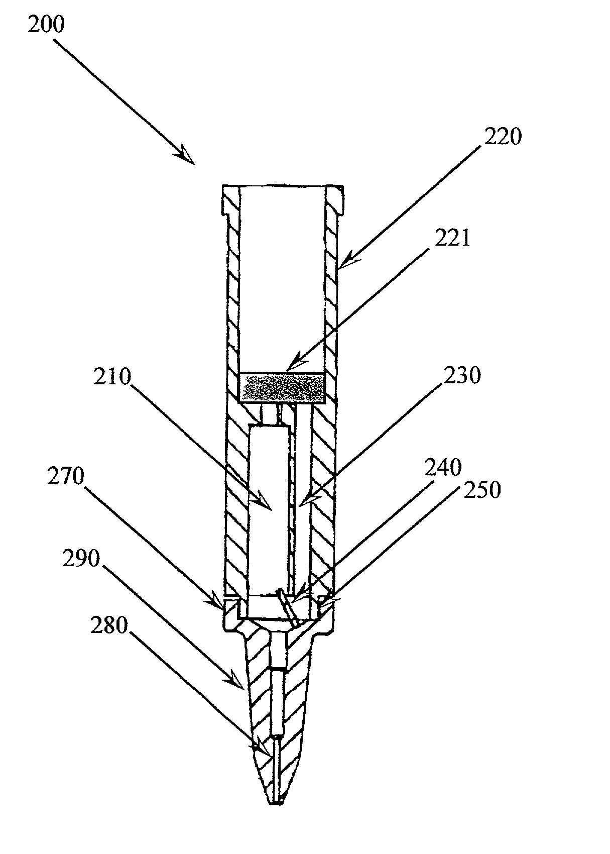
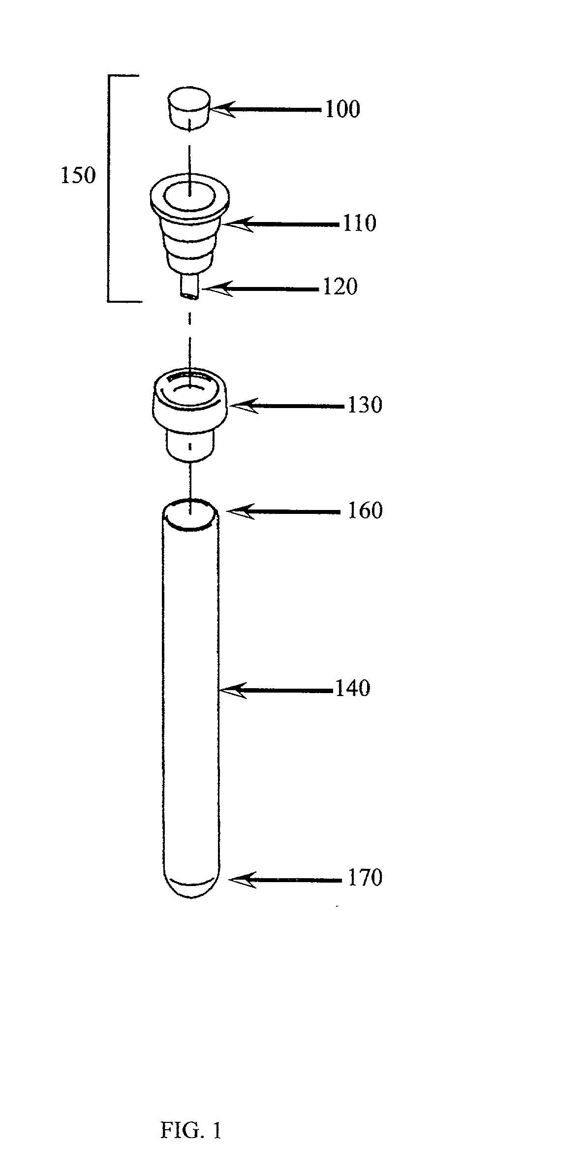
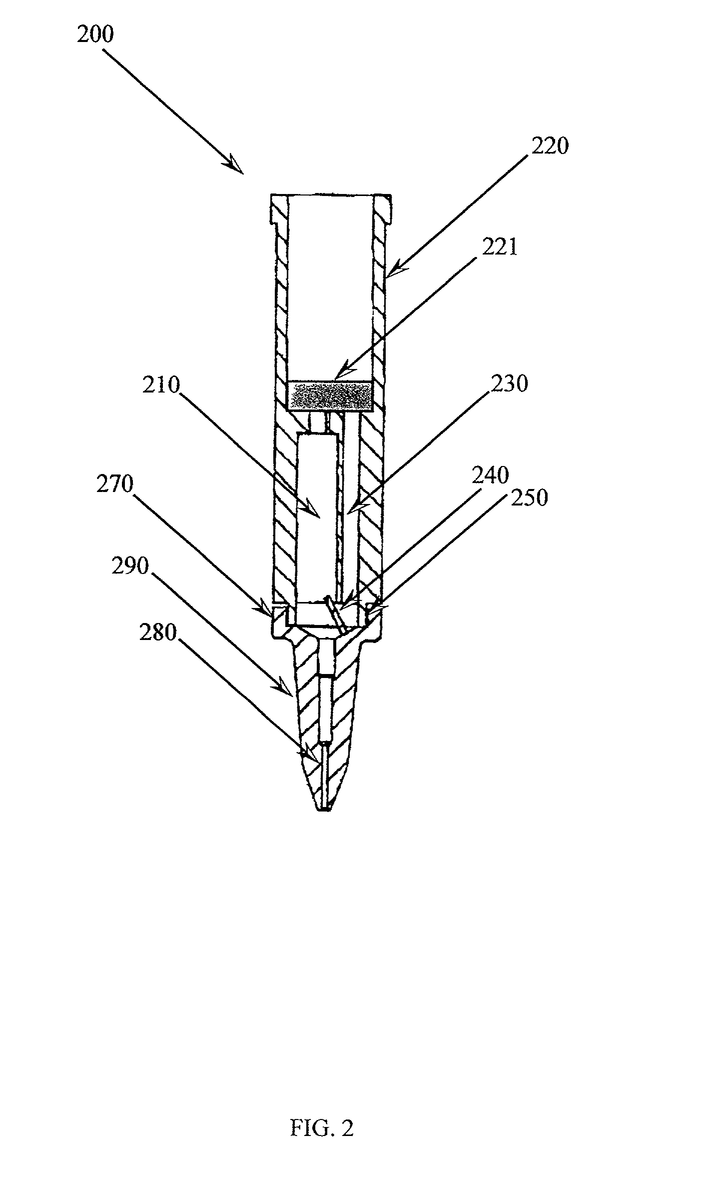
Pipette sampling system
a sampling system and pipette technology, applied in sampling, laboratory glassware, instruments, etc., can solve the problems of limiting the rate-limiting steps of the complete process, limiting the ability to generate nucleotide sequence information, and limited the processing of small samples per day. , to achieve the effect of preventing cross-contamination
- Summary
- Abstract
- Description
- Claims
- Application Information
AI Technical Summary
Benefits of technology
Problems solved by technology
Method used
Image

Examples
example 1
[0077] Loading of Sample Tube
[0078] A Vacutainer.TM. specimen tube was filled with blood and capped. The specimen tube was positioned upright within the loading arm and held in place by inflatable membrane holders.
example 2
[0079] Piercing of Sample Tube
[0080] The piercing tip of the pipette tip was positioned above the capped end of the specimen tube by the loading arm. The puncture cylinder pushed the pipette tip downward to reversibly engage and pierce the specimen tube.
example 3
[0081] Aspiration of Sample from Sample Tube
[0082] The specimen tube and the pipette tip were rotated about 180 degrees, wherein the specimen tube was substantially inverted. An aliquot of blood was aspirated out of the specimen tube and into the hollow chamber of the pipette tip. The puncture cylinder retracted the pipette tip, thereby disengaged the piercing tip from the specimen tube. The specimen tube was inverted into a substantially upright position. The aliquot of blood was processed by any method known in the art to yield purified DNA.
PUM
| Property | Measurement | Unit |
|---|---|---|
| volume | aaaaa | aaaaa |
| volume | aaaaa | aaaaa |
| volume | aaaaa | aaaaa |
Abstract
Description
Claims
Application Information