Load cell

a load cell and load technology, applied in the field of load cells, can solve the problems of reducing the life of the load cell, difficult to ensure a high weight detection precision, and rapid expansion of corrosion, so as to improve the resistance to water, rust and corrosion, and achieve high weight detection precision.

Inactive Publication Date: 2002-10-03
ISHIDA CO LTD
View PDF0 Cites 19 Cited by
  • Summary
  • Abstract
  • Description
  • Claims
  • Application Information

AI Technical Summary

Benefits of technology

0016] Also an object of the invention is to provide a load cell, which has improved resistance to water, rust and corrosion, and can achieve high weight detection precision.

Problems solved by technology

Therefore, if an atmosphere containing oxygen and / or moisture is present around these connections, electricity flows between the dissimilar metal materials to cause galvanic corrosion so that corrosion expands rapidly to reduce a lifetime of the load cell.
However, it is difficult to ensure a high weight detection precision, and particularly, it is difficult to use the stainless steel instead of aluminum from the viewpoint of a processing or working cost.
However, the molded material, which is present between the member on the measuring target side or fixed base side and the strain body, deteriorates a weight detection precision due to viscoelastic properties of the molded material.
Also, deformation of the molded material caused by the load deteriorates the weight detection precision.
However, this requires a complicated work for molding, and increases a working cost.
However, this cannot prevent the galvanic corrosion.
However, this requires a devised structure for preventing restraint on movements of the measuring target side member and the movable portion of the strain body, resulting in disadvantages relating to the cost and size.
In this manner, however, water enters a fine space between the strain body and the film to cause corrosion.
In this manner, however, the load of the measuring target object is not transmitted 100% to the load cell so that an error occurs in a result of measurement.
If a scale including the strain body is used, e.g., in hot and humid surroundings or in a place exposed to salt-laden moisture of seawater or the like, corrosion occurs on the contact surfaces of dissimilar metal materials, and is also liable to occur on other surfaces.
In the above structure, since the coating film is interposed between the strain body and the dissimilar metal member attached thereto the degree of fixing between the strain body and the dissimilar metal member may be lowered, and the weight detection precision may be adversely affected.
However, these disadvantages are extremely smaller than the disadvantages caused by a thick molded member or other thick members for the insulation.
Particularly, if the weighing capacity is small (10 kg or lower), the viscosity properties exert a large influence, which cannot be substantially corrected.
As already described, if a conventional structure is provided with an insulating film between the surfaces of the strain body and the dissimilar metal member, water enters a space to cause corrosion.
If a soft material is interposed, a load of the measuring target object is not accurately transmitted to the load cell, resulting in a measuring error.
Copper-contained aluminum alloy, which is generally used in load cells, cannot have sufficient resistance to galvanic corrosion even if anodizing is effected on the surface because the anodized aluminum film thus formed have many defects.
In a conventional structure including a molded material, which has a thickness from hundreds of micrometers to several millimeters, and is present between the strain body and the dissimilar metal member, it is probably impossible to maintain the intended weight detection precision.
If the thickness of the coating film were excessively small, and did not exceed one .mu.m, a damage would often occur on the coating film so that the load cell could not have intended water resistance.
If the thickness were larger than 100 .mu.m, the detection precision of the sensor would be excessively low.
In the load cell 1, the coating film 10 interposed between the strain body 2 and the connection members 81 and 91 may lower the degree of fixing between them, and thus may adversely affect the weight detection precision.
However, even if the strain gauge 7 is adhered onto the coating film 10, an adverse effect exerted on the detection result of the strain gauges 7 by the coating film 10 may be extremely small, or the provision of the coating film 10 may hardly affect the detection result of the strain gauges 7 because the thickness t of the coating film 10 is extremely small.

Method used


Image

  • Load cell
  • Load cell
  • Load cell

Examples


Embodiment Construction

[0153]

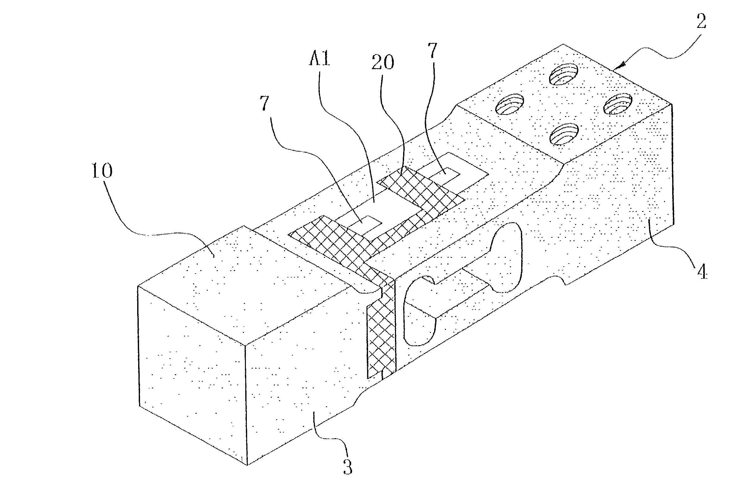
[0154] Evaluations were performed on the rustproof performance of the structure having the coating film 10 over the strain body 2.

[0155] First, the strain body 2 made of copper-contained aluminum alloy of No. 2000 series was prepared, and then the anodizing was effected on the strain body 2, of which a portion used for attaching the strain gauges 7 is masked. The anodized portion of the strain body 2 was subjected to spray coating with organic / inorganic hybrid paint ("BELL CLEAN No. 1000" manufactured by NOF Corporation) to form the coating layer.

[0156] In this implementation example, the coating was also applied to screw portions near or around the screw holes 3a and 4a. However, application of the paint to these portions is not essential.

[0157] After the application of the paint, the strain gauges 7 were attached to the strain body 2 (implementation example 1).

[0158] As a comparison example, the strain body 2 was prepared and processed similarly to the implementation exampl...


PUM

PropertyMeasurementUnit
glass transition temperatureaaaaaaaaaa
thicknessaaaaaaaaaa
thicknessaaaaaaaaaa

Abstract

A load cell 1 includes a strain body 2, a bridge circuit and a coating film 10. The bridge circuit is formed of a strain gauge 7 arranged on the strain body 2. The coating film 10 is formed on the strain body 2, covers at least a portion of the strain body 2 attached to a member made of a metal material dissimilar to the strain body and a strain occurring portion of the strain body 2 except for a portion to be attached to the strain gauge 7, includes a coating layer made of resin having a glass transition temperature of 40° C. or more, and has an electrical insulating property.

Description

This is a continuation-in-part of International Application PCT / JP01 / 04574, with an international filing date of May 30, 2000, not yet published.[0001] 1. Field of the Invention[0002] The present invention relates to a load cell, and particularly to a load cell provided with a strain body and a sensor for detecting a displacement of the strain body caused by a load.[0003] 2. Background Information[0004] In general, a load cell used in a measuring device or the like has a strain body (i.e., a body to be strained) having a movable portion and a fixed portion, and a sensor for detecting a displacement of a strain body caused by a load applied thereto. A result of the detection is converted into a weight of a measuring target object, i.e., an object to be measured.[0005] The movable portion of the strain body of the load cell is fixed to a support member supporting the measuring target object, or is fixed to a connection member, which connects the support member to the strain body, and ...

Claims


Application Information

Patent Timeline
Patent Type & Authority Applications(United States)
IPC IPC(8): G01G3/14G01L1/22
CPCG01L1/2243G01G3/1412G01G3/14
Inventor CHIMURA, YUKIKOWAKASA, YUKIO
Owner ISHIDA CO LTD
Why Eureka
Try Eureka