Magnetically biasing bond magnet for improving DC superposition characteristics of magnetic coil

a magnetic coil and superposition characteristic technology, applied in the direction of magnets, transformers/inductances magnetic cores, magnetic bodies, etc., can solve the problems of difficult to determine good and bad of magnetic cores for choke coils and transformers by core temperature measuremen

Inactive Publication Date: 2002-10-17
TOKIN CORP
View PDF3 Cites 19 Cited by
  • Summary
  • Abstract
  • Description
  • Claims
  • Application Information

AI Technical Summary

Problems solved by technology

The saturation magnetization is inevitably determined by materials and cannot be made as high as desired.
The magnetic bias by use of the permanent magnet is a good solution to improve the DC superposition characteristic, but it have hardly been brought into a practical use because use of a sintered metallic magnet resulted in considerable increase of a core loss of the magnetic core, while use of a ferrite magnet led in unstable superposition characteristic.
Recently, a power supply has been more and more strongly required to improve its power transformation efficiency to such a high level that it is difficult to determine good and bad of magnetic cores for choke coils and transformers by core temperatures measured.
Therefore, it is inevitable to determine it from core loss data measured by use of a core-loss measuring device.

Method used


Image

  • Magnetically biasing bond magnet for improving DC superposition characteristics of magnetic coil
  • Magnetically biasing bond magnet for improving DC superposition characteristics of magnetic coil
  • Magnetically biasing bond magnet for improving DC superposition characteristics of magnetic coil

Examples


example 1

Relation Between Specific Resistance and Core-loss

[0137]

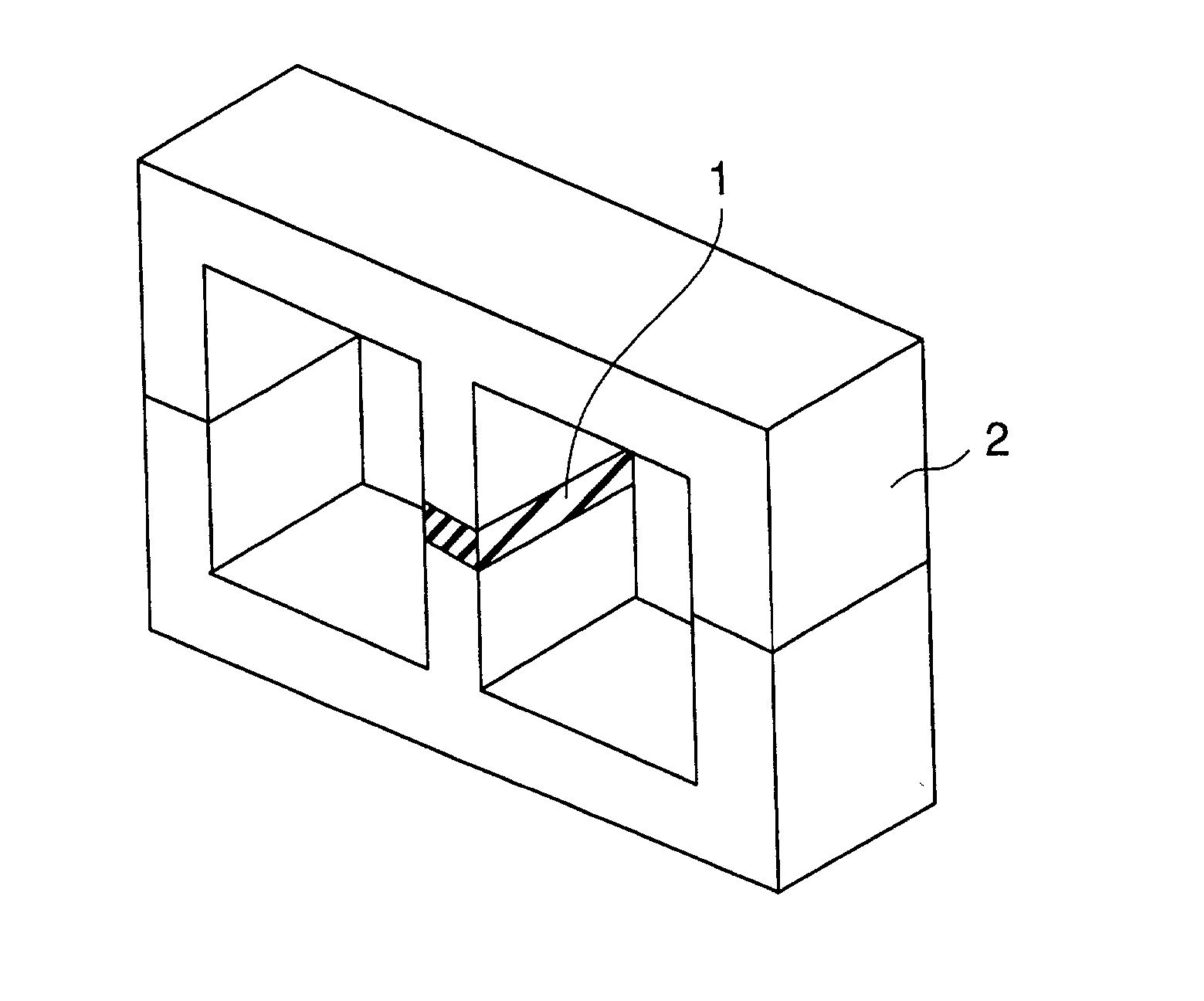
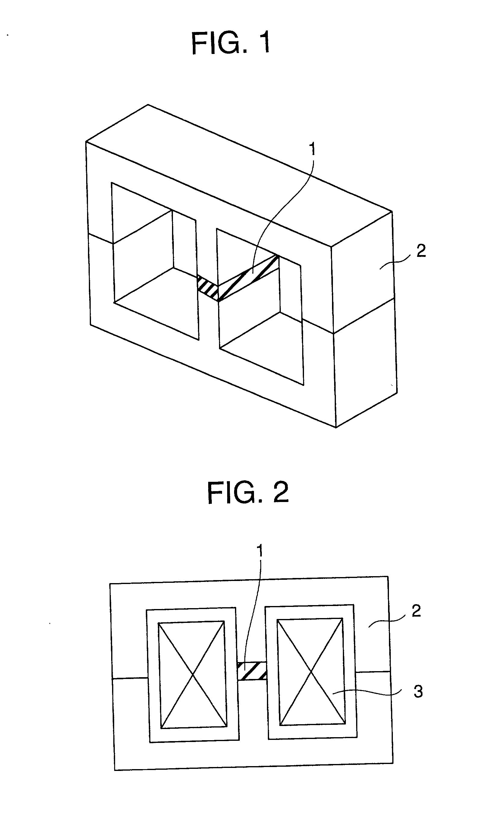
1 Magnetic powder: Sm.sub.2Fe.sub.17N.sub.3 Average particle size: 3 .mu.m Intrinsic coercive force iHc: 10.5 kOe Curie point Tc: 470.degree. C. Binder: Epoxy resin Amount (volume %): Adjusted to obtain following specific resistances Production method of Magnet: Molding, without aligning magnetic field Magnet: Thickness T: 1.5 mm Shape and Area: corresponding to the section of a middle leg of E-shape core Specific resistance (.OMEGA. .multidot. cm): S-1: 0.01 S-2: 0.1 S-3: 1 S-4: 10 S-5: 100 Intrinsic coercive force: 5 kOe or more Magnetization: Electromagnet Magnetic core: E-E core (FIGS. 1 and 2), MnZn ferrite Magnetic gap length G: 1.5 mm Measurement of Core-loss: Measured at f = 100 kHz, Ha = 0.1 T (Tesla) Measurement of DC superposition characteristics (magnetic permeability .mu.): Measured at f = 100 kHz, Hm = 100 Oe

[0138] The same magnetic core is used for each of samples and the core-loss measured in each sample is show...

example 2

Relation Between Particle Size of Magnetic Powder and Core-loss

[0141]

3 Magnetic powder: Sm.sub.2Co.sub.17 Curie point Tc: 810.degree. C. Energy Product: 28MGOe S-1: Maximum particle size: 200 .mu.m Intrinsic coercive force iHc: 12 kOe S-2: Maximum particle size: 175 .mu.m Intrinsic coercive force iHc: 12 kOe S-3: Maximum particle size: 150 .mu.m Intrinsic coercive force iHc: 12 kOe S-4: Maximum particle size: 100 .mu.m Intrinsic coercive force iHc: 12 kOe S-5: Maximum particle size: 50 .mu.m Intrinsic coercive force iHc: 11 kOe Binder: Epoxy resin Resin content: 10 weight % in each sample Production method of Magnet: Molding, without aligning magnetic field Magnetization: Electromagnet Magnet: Thickness T: 0.5 mm Shape and Area: 7 mm .times. 10 mm Specific resistance: S-1: 1.2 .OMEGA. .multidot. cm S-2: 1.5 .OMEGA. .multidot. cm S-3: 2.0 .OMEGA. .multidot. cm S-4: 3.0 .OMEGA. .multidot. cm S-5: 5.0 .OMEGA. .multidot. cm Intrinsic coercive force: Same as magnetic powder Magnetic core...

example 3

Relation Between Coercive Force of Magnet and DC Superposition Characteristics (Magnetic Permeability)

[0145]

5 Magnetic powder: S-1: Ba ferrite Intrinsic coercive force iHc: 4.0 kOe Curie point Tc: 450.degree. C. S-2: Sm.sub.2Fe.sub.17N.sub.3 Intrinsic coercive force iHc: 5.0 kOe Curie point Tc: 470.degree. C. S-3: Sm.sub.2Co.sub.17 Intrinsic coercive force iHc: 10.0 kOe Curie point Tc: 810.degree. C. Particle size (Average): 3.0 .mu.m in all samples Binder: Polypropylene resin (Softening point 80.degree. C.) in each sample Amount: 50 volume % Production method of Magnet: Molding, without aligning magnetic field Magnet: Thickness T: 1.5 mm Sectional shape: corresponding to the section of a middle leg of the core Specific resistance: S-1: 10.sup.4.OMEGA. .multidot. cm or more S-2: 10.sup.3.OMEGA. .multidot. cm or more S-3: 10.sup.3.OMEGA. .multidot. cm or more Intrinsic coercive force: Same as magnetic powder Magnetization: Pulse magnetization machine Magnetic core: E-E core (FIGS. 1 ...


PUM

PropertyMeasurementUnit
particle sizeaaaaaaaaaa
Curie point Tcaaaaaaaaaa
particle sizeaaaaaaaaaa

Abstract

In order to provide an inductance part having excellent DC superposition characteristic and core-loss, a magnetically biasing magnet, which is disposed in a magnetic gap of a magnetic core, is a bond magnet comprising magnetic powder and plastic resin with the content of the resin being 20% or more on the base of volumetric ratio and which has a specific resistance of 0.1 OMEGA.cm or more. The magnetic powder used is rare-earth magnetic powder having an intrinsic coercive force of 5 kOe or more, Curie point of 300° C. or more, and an average particle size of 2.0-50 mum. A magnetically biasing magnet used in an inductance part that is treated by the reflow soldering method has a resin content of 30% or more and the magnetic powder used therein is Sm-Co magnetic powder having an intrinsic coercive force of 10 kOe or more, Curie point of 500° C. or more, and an average particle size of 2.5-50 mum. A thin magnet having a thickness of 500 m or less can be realized for a small-sized inductance part.

Description

[0001] This invention relates to a permanent magnet for magnetically biasing a magnetic core (which will hereinunder be often referred to as "core" simply) which is used in an inductance element such as a choke coil, transformer or the like. Further, this invention relates to a magnetic core having a permanent magnet as a magnetically biasing magnet and an inductance element using the magnetic coil.BACKGROUND TECHNIQUE[0002] To a choke coil and a transformer used in, for example, a switching power supply or the like, an AC current is usually applied thereto together with a DC current superposed thereto. Therefore, a core used in those choke coil and transformer is required to have a magnetic characteristic of a good magnetic permeability so that the core is not magnetically saturated by the superposition of the DC current (the characteristic will be referred to as "DC superposition characteristic" or simply as "superposition characteristic").[0003] As magnetic cores in application f...

Claims


Application Information

Patent Timeline
Patent Type & Authority Applications(United States)
IPC IPC(8): H01F1/055H01F3/10H01F3/14H01F17/04H01F29/14
CPCH01F1/0552H01F1/0558H01F3/10H01F2003/103H01F17/04H01F29/146H01F3/14H01F1/04
Inventor FUJIWARA, TERUHIKOISHII, MASAYOSHIHOSHI, HARUKIISOGAI, KEITAMATSUMOTO, HATSUOITO, TORUAMBO, TAMIKO
Owner TOKIN CORP
Why Eureka
Try Eureka