
Method for fabricating ruthenium thin layer

a thin layer and ruthenium technology, applied in the direction of coatings, solid-state devices, chemical vapor deposition coatings, etc., can solve the problem of particle generation

Inactive Publication Date: 2002-11-21
SK HYNIX INC
View PDF9 Cites 88 Cited by
  • Summary
  • Abstract
  • Description
  • Claims
  • Application Information

AI Technical Summary

Problems solved by technology

These non-volatile materials exist in the Ru thin layer and cause generation of particles.

Method used


Image

  • Method for fabricating ruthenium thin layer
  • Method for fabricating ruthenium thin layer
  • Method for fabricating ruthenium thin layer

Examples


Embodiment Construction

[0017] Hereinafter, methods for fabricating a ruthenium (Ru) thin layer will be described in detail referring to the accompanying drawings.

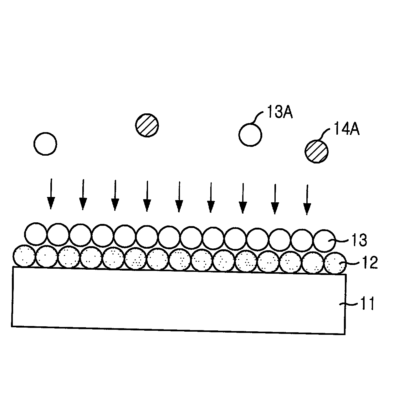
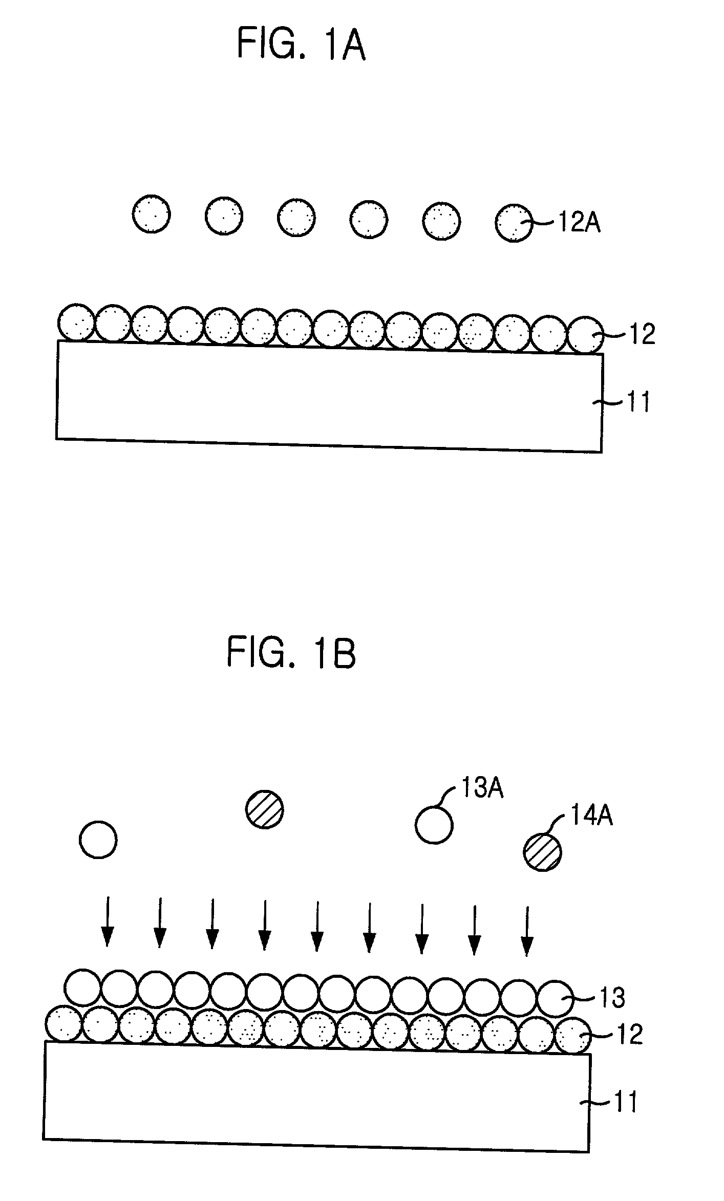
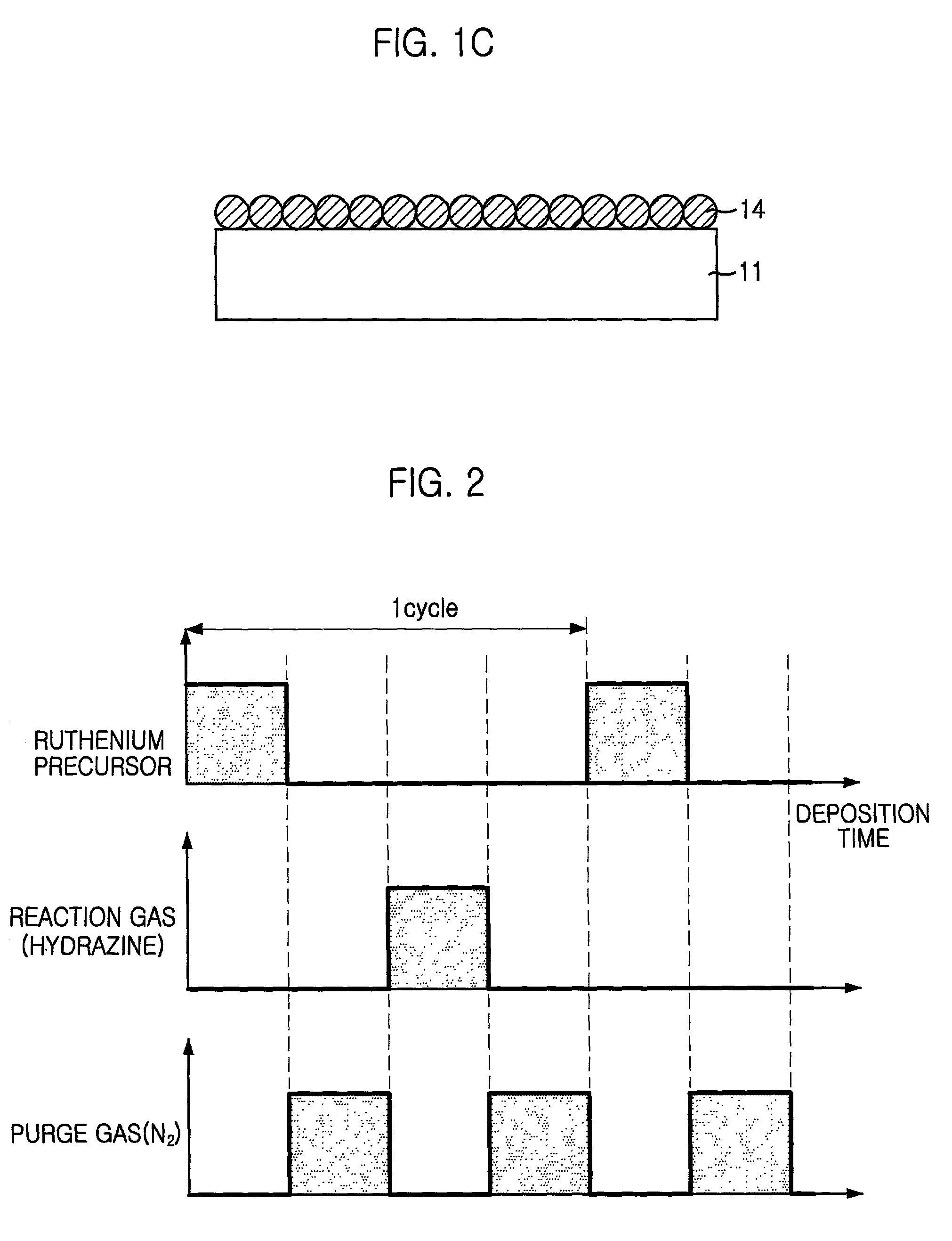
[0018] A method for fabricating the Ru thin layer according to one embodiment of the disclosure will be described. RuX.sub.2 and RuX.sub.3 materials, of which oxidation states are of +2 and +3 respectively, are used as a Ru precursor and a hydrazine (N.sub.2H.sub.4) is used as a reaction gas. Hydrazine is a compound of nitrogen and hydrogen. Hydrazine smokes in air and is a transparent liquid. Also, hydrazine smells like ammonia and has a melting point, boiling point and specific gravity of 2.degree. C., 113.5.degree. C. and 1.021 g / cm.sup.3, respectively.

[0019] The reaction of the Ru precursor and the hydrazine is as follows:

RuX.sub.2+2N.sub.2H.sub.4.fwdarw.Ru+2HX+2NH.sub.3+N.sub.2,

RuX.sub.3+3Me.sub.2NNH.sub.2.fwdarw.Ru+3HX+3NHMe.sub.2+{fraction (3 / 2)}N.sub.2

[0020] Where, X is a material selected from the group consisting of H, C.sub.1.about.C.s...


PUM

PropertyMeasurementUnit
timeaaaaaaaaaa
temperatureaaaaaaaaaa
boiling pointaaaaaaaaaa

Abstract

A method for fabricating a Ru thin layer by using an atomic layer deposition (ALD) technique is disclosed. The method comprises the steps of loading a substrate into a reaction chamber for an atomic layer deposition, adsorbing RuXn (wherein n is 2 or 3), which is a Ru precursor, onto the substrate and injecting a reductive reaction gas into the reaction chamber.

Description

[0001] The present invention relates to a method for fabricating a thin layer, and, more particularly, to a method for fabricating a ruthenium (Ru) thin layer by using an atomic layer deposition (ALD) technique.DESCRIPTION OF THE RELATED ART[0002] A chemical vapor deposition (CVD) technique has been used to deposit a layer on a substrate such as a silicon wafer. A precursor used in the CVD technique is a thermally decomposed volatile compound to be adsorbed into a heated substrate at a temperature that exceeds the decomposition temperature. Layers, such as a metal, a metal mixture, a metal alloy, a ceramic, a metal compound and a mixture thereof, are deposited by the CVD technique, dependent on selection of and reaction conditions of a precursor.[0003] A ruthenium (Ru) layer formed by the CVD technique in an integrated circuit process of a semiconductor device has an excellent conductivity, a high stability in a wide temperature range and a good adhesion with a silicon layer, a sili...

Claims


Application Information

Patent Timeline
Patent Type & Authority Applications(United States)
IPC IPC(8): C23C16/18C23C16/455H01L21/205H01L21/285H10B20/00
CPCC23C16/18H01L21/28562C23C16/45553H01L21/28556H01L28/65
Inventor KIM, YOUNSOO
Owner SK HYNIX INC
Learn More