Ion sampling for APPI mass spectrometry

a mass spectrometry and appi technology, applied in the direction of particle separator tube details, instruments, separation processes, etc., can solve the problems of poor reproducibility, poor performance of flow splitters, and problems such as plugging

Inactive Publication Date: 2002-12-05
AGILENT TECH INC
View PDF0 Cites 21 Cited by
  • Summary
  • Abstract
  • Description
  • Claims
  • Application Information

AI Technical Summary

Problems solved by technology

However, the use of flow splitters has performed poorly in that they experience plugging problems and poor reproducibility.
It is a desired feature of an assisted nebulizer system that the vacuum system leading to the mass spectrometer permit desolvated ions to enter, but do not permit relatively large solvated droplets present in the electrosprayed aerosol to enter.
Several design approaches are currently in use, but none of the assisted nebulization methods currently practiced provide reliable sensitivity along with robust instrumentation.
Optimal performance appears to be limited to a flow rate of 200 microliters per minute or lower.
This system has several disadvantages and limitations, including sample degradation, re-clustering, and loss of sensitivity.
While these clusters may be re-dissociated by collisionally induced processes, this may interfere in identification of structural characteristics of the analyte samples.
One disadvantage of this configuration is that optimal performance is effectively limited to less than five hundred (500) microliters per minute.
Adequate handling of the aqueous mobile phase is problematic.
Furthermore, the apparatus is complex and prone to mechanical and electronic failures.
Although this works competitively, there is still some noise which is probably due to stray droplets.
Thus, repeated and tedious adjustments are often required.
However, there are still analytes that do not ionize at all when these ionization techniques are employed, or which ionize weakly when these ionization techniques are employed.
Collisions between the photons and the analyte result in ionization of the analyte.
Then subsequent collisions between the ionized dopant and the analyte result in ionization of the analyte.
Configurations for APPI in present use often provide unsatisfactory signal relative to noise and do not provide for optimal ion collection efficiency.

Method used


Image

  • Ion sampling for APPI mass spectrometry
  • Ion sampling for APPI mass spectrometry
  • Ion sampling for APPI mass spectrometry

Examples


Embodiment Construction

[0048] A number of different configurations have been proven possible. Examples of certain tested configurations follow:

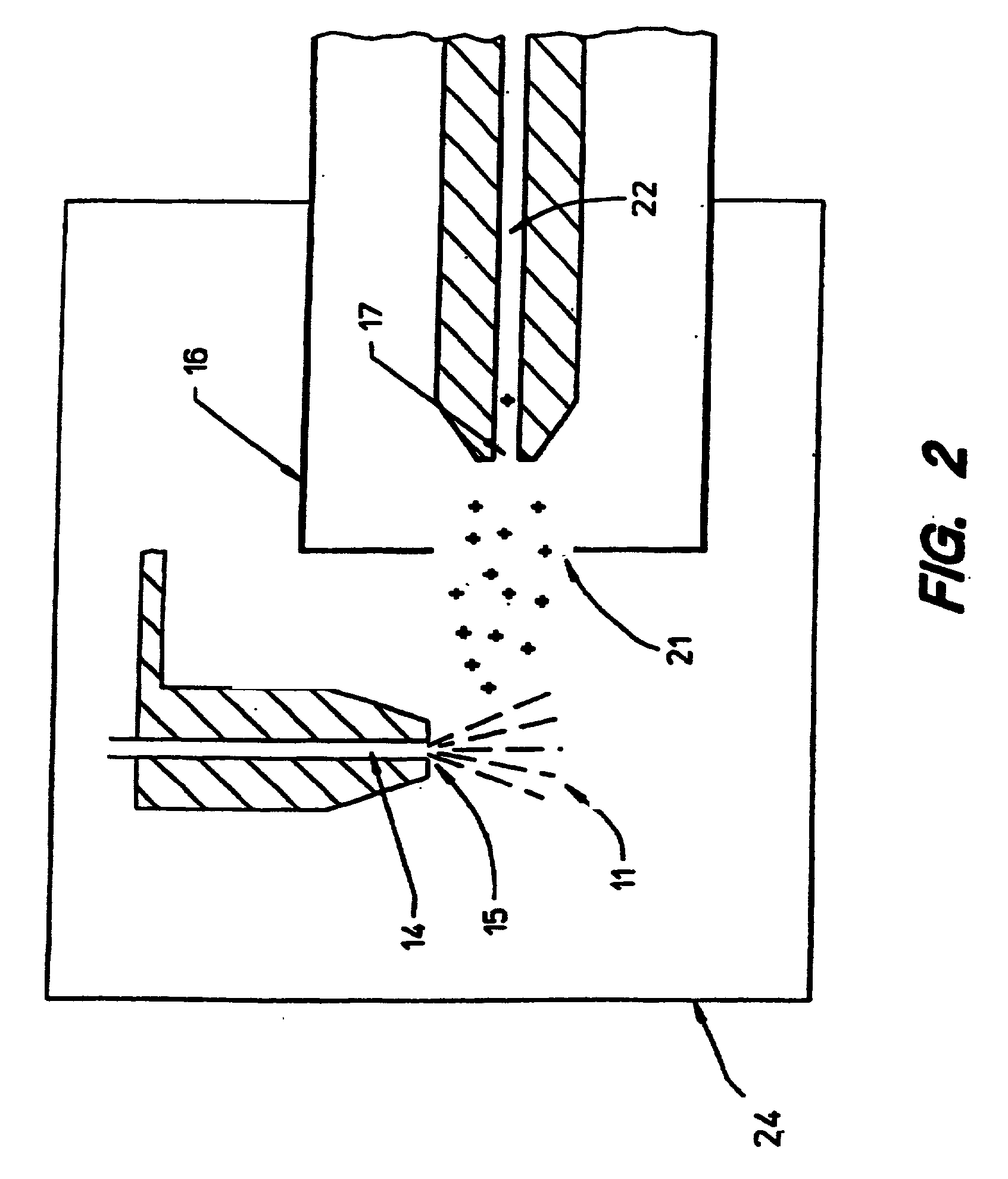
[0049] FIG. 2 shows a configuration of the invention in which a third voltage source, a plate 24, is positioned beside the exit 15 of the first passageway 14 and distal to the side near to which the first voltage source, the opening 21 in the housing 16, and the opening 17 to the second passageway 22 are positioned. The plate 24 runs a positive voltage relative to the charge on the housing 16. Experiments show the electrosprayed aerosol "sees" a mean voltage between the plate 24 and the charged housing 16. Results suggest that the repeller effect may be captured and ion collection yield increased by careful sculpting of both the electric field and the gas flow patterns.

[0050] FIG. 3 shows a two-voltage source system as in FIG. 2 with the addition of a grounded spray chamber 26. The spray chamber 26 operates to contain the electrosprayed aerosol and route condensed ...


PUM

PropertyMeasurementUnit
angleaaaaaaaaaa
angleaaaaaaaaaa
angleaaaaaaaaaa

Abstract

An atmospheric pressure ion source, e.g. for a mass spectrometer, that produces ions by atmospheric pressure photoionization (APPI). It includes a vaporizer, a photon source for photoionizing vapor molecules upon exit from the vaporizer, a passageway for transporting ions to, for example, a mass spectrometer system, and a means for directing the ions into the passageway. The center axis of the vaporizer and the center axis of the passageway form an angle that may be about 90 degrees. Included in the invention is a method for creating ions by atmospheric pressure photoionization along an axis and directing them into a passageway oriented at an angle to that axis.

Description

[0001] This application is a continuation-in-part of U.S. patent application Ser. No. 09 / 910,222 filed Jul. 20, 2001, which is a continuation of U.S. patent application Ser. No. 09 / 204,213 filed Dec. 2, 1998 (now U.S. Pat. No. 6,294,779, issued Sep. 25, 2001), which is a continuation of U.S. patent application Ser. No. 09 / 030,676 filed Feb. 25, 1998 (now U.S. Pat. No. 6,278,110, issued Aug. 21, 2001), which is a continuation of U.S. patent application Ser. No. 08 / 794,248 filed Feb. 3, 1997 (now U.S. Pat. No. 5,750,988, issued May 12, 1998), which is a continuation of U.S. patent application Ser. No. 08 / 555,250, now abandoned, which is a continuation-in-part of U.S. patent application Ser. No. 08 / 273,250 filed Jul. 11, 1994 (now U.S. Pat. No. 5,495,108, issued Feb. 27, 1996).[0002] The present invention relates to a method and apparatus for obtaining improved signal relative to noise without loss of ion collection efficiency for use in mass spectrometry, including liquid chromatograp...

Claims


Application Information

Patent Timeline
Patent Type & Authority Applications(United States)
IPC IPC(8): G01N30/72H01J49/04
CPCG01N30/7253H01J27/24H01J49/162H01J49/145H01J49/0431
Inventor FISCHER, STEVEN M.GOURLEY, DARRELL L.CORMIA, PATRICIA H.BERTSCH, JAMES L.
Owner AGILENT TECH INC
Why Eureka
Try Eureka