Measurement device including a pressure sensor

a pressure sensor and measurement device technology, applied in the direction of capacitors, instruments, electrical equipment, etc., can solve the problems of contaminating the fluid flowing in the pipe, causing a dead space in front of the isolating disk, and unable to clean so as to facilitate cleaning the pipe or the vessel, reduce wear and abrasion, and increase the range of materials that can be used.

Inactive Publication Date: 2002-12-19
REGULATEURS GEORGIN
View PDF7 Cites 11 Cited by
  • Summary
  • Abstract
  • Description
  • Claims
  • Application Information

AI Technical Summary

Benefits of technology

0009] The invention makes it possible to use the measurement device without it being necessary for the wall surrounding the sensor to be pressed against a flange or against a step in the tapping hole in the pipe or the vessel that receives the device. The invention thus makes it possible to avoid creating a dead space in front of the measurement device because it is possible to position the outside surface of the coating flush with the inside surface of the pipe or the vessel. The device of the invention is thus entirely compatible with being used in the pharmaceutical or the food industry, in particular.
0010] Furthermore, because of the adhesion of the coating to the sensor and to the wall of the device surrounding it, it is possible to measure a negative pressure, and that constitutes an additional advantage.
0011] The coating used is preferably non-stick, e.g. having a coefficient of friction that is less than or equal to 0.3, more preferably less than or equal to 0.15, so as to avoid disturbing fluid flow, so as to facilitate cleaning the pipe or the vessel, and so as to reduce wear by abrasion.
0012] In a preferred embodiment, the sensor is stuck to the inside of a ring which is fitted to the coupling. The ring preferably has an inside section that matches the shape of the sensor, and it need not be circular in shape. Such a ring increases the range of materials that can be used since the ring and the coupling need not be made of the same material. The ring can also make it easier to perform the operation of depositing the coating, since it is easier to handle than the coupling, which is bulkier. The ring is preferably made of metal, e.g. stainless steel, thus providing good adhesion for the materials suitable for use in forming the coating, and m...

Problems solved by technology

That solution does not provide entire satisfaction since the metal diaphragm can break and allow the pressure-transmitting liquid to escape, thereby contaminating the fluid flowing in the pipe.
That measurement device presents the advantage of avoiding the use of a pressure-transmitting liquid and eliminates the risks associated therewith, but it presents the drawbacks ...

Method used


Image

  • Measurement device including a pressure sensor
  • Measurement device including a pressure sensor
  • Measurement device including a pressure sensor

Examples


Embodiment Construction

[0046] Throughout the specification, including in the claims, the term "comprising a" should be understood as being synonymous with "comprising at least one", unless the contrary is specified.

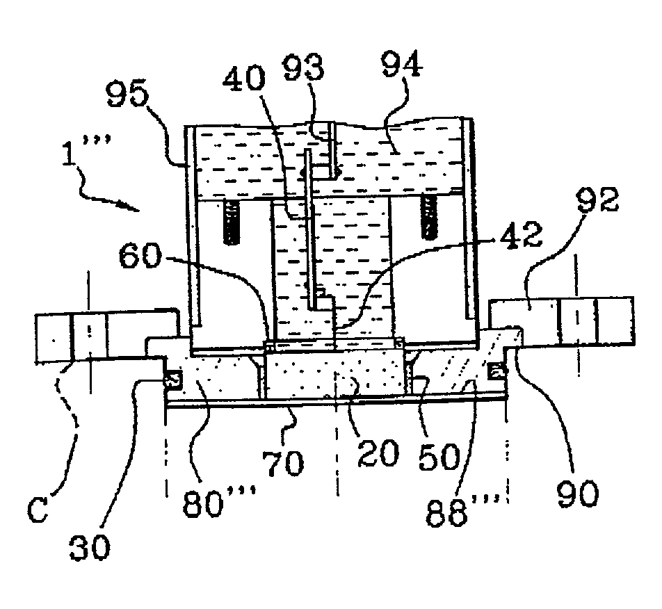
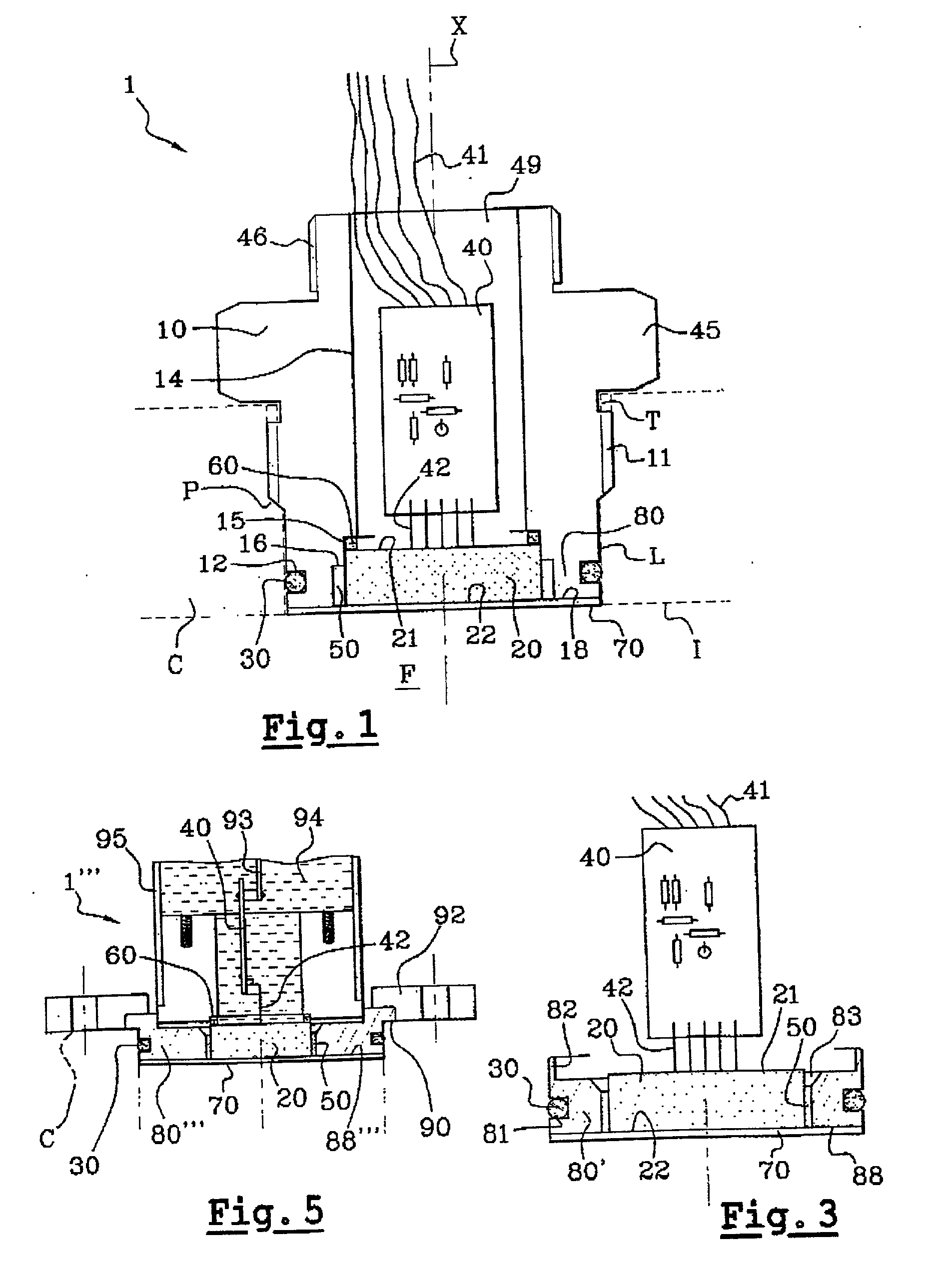
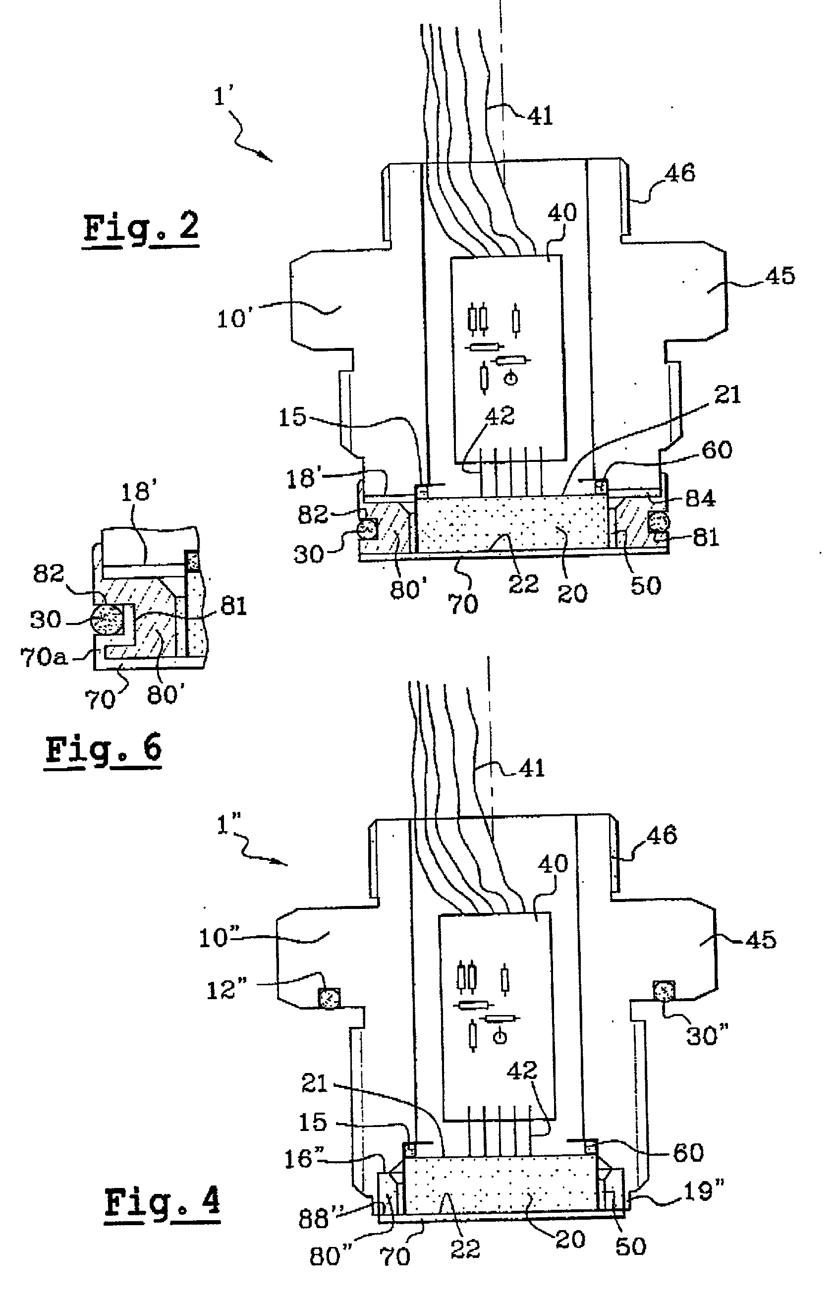
[0047] FIG. 1 shows a pressure measurement device 1 comprising both a metal coupling 10 made of stainless steel, and a pressure sensor 20. The sensor 20 is known per se and comprises a ceramic diaphragm having an electrical circuit 20a for measuring pressure formed thereon, said circuit comprising resistive tracks 200 as shown in FIG. 7 and a ceramic support with tinned electrical connections passing therethrough connecting the ends of the conductor tracks made on the ceramic diaphragm with the inside face 21 of the sensor 20. The invention is not limited to a sensor of resistive type, and it can be applied to sensors of capacitive type, for example. The sensor 20 further comprises a temperature sensor comprising a temperature-sensitive resistor 20b close to the resistor tracks 200 on the ceram...


PUM


Abstract

The present invention relates to a measurement device for fixing to a pipe or a vessel containing a fluid, the device comprising a pressure sensor surrounded by a wall. The device includes a coating adhering to said wall and suitable for isolating the fluid sensor.

Description

[0001] The present invention relates to measuring the pressure of a fluid, i.e. a gas or a liquid, and also where appropriate its temperature, particularly but not exclusively in the pressure range -1 bar (-10.sup.5 Pascals (Pa)) to 600 bars (6.times.10.sup.7 Pa).[0002] In order to measure the pressure of a fluid flowing in a pipe, it is known to use a measurement device comprising a coupling for fixing in a tapping hole in the pipe and a ceramic-diaphragm pressure sensor fixed to the coupling. The ceramic diaphragm has resistor tracks on one face that are connected as a Wheatstone bridge, as shown in FIG. 7, and the deformations of the diaphragm under the effect of pressure unbalance the bridge, with said unbalance being detected by electronic means that are suitable for generating a signal that is representative of the pressure.[0003] Proposals have been made, in particular in the food industry, to use pressure-measuring devices in which the pressure sensor is isolated from the fl...

Claims


Application Information

Patent Timeline
IPC IPC(8): G01L9/00G01L19/00G01L19/04G01L19/06G01L19/14
CPCG01L19/0092G01L19/04G01L19/148G01L19/141G01L19/147G01L19/0627
Inventor DOUBROVSKY, GILLES LOUIS
Owner REGULATEURS GEORGIN
Why Eureka
Try Eureka