Scanning interferometry with reference signal

US20020196450A1Inactive Publication Date: 2002-12-26BRUKER NANO INC

Image

  • Scanning interferometry with reference signal
  • Scanning interferometry with reference signal
  • Scanning interferometry with reference signal

Examples


Embodiment Construction

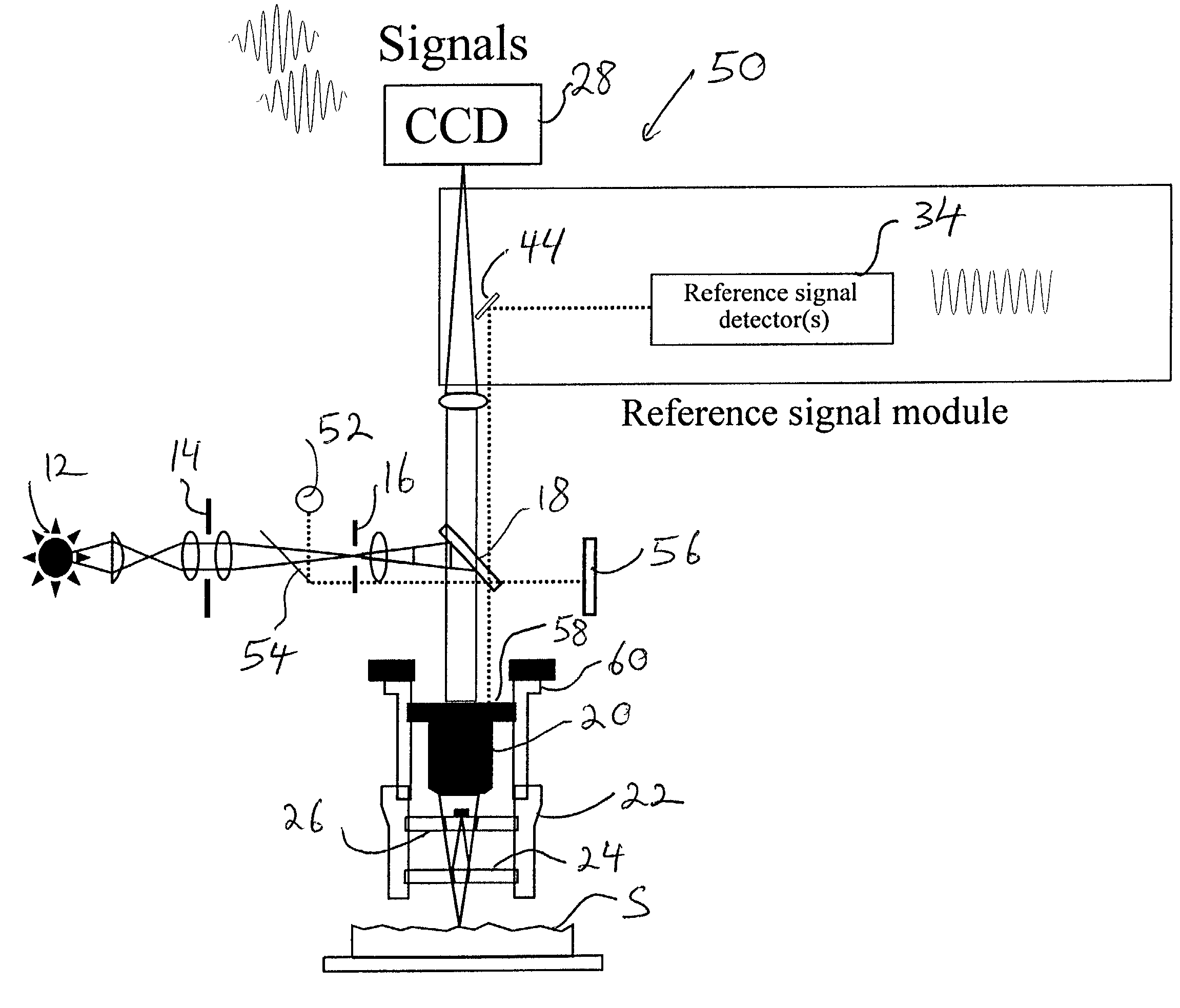
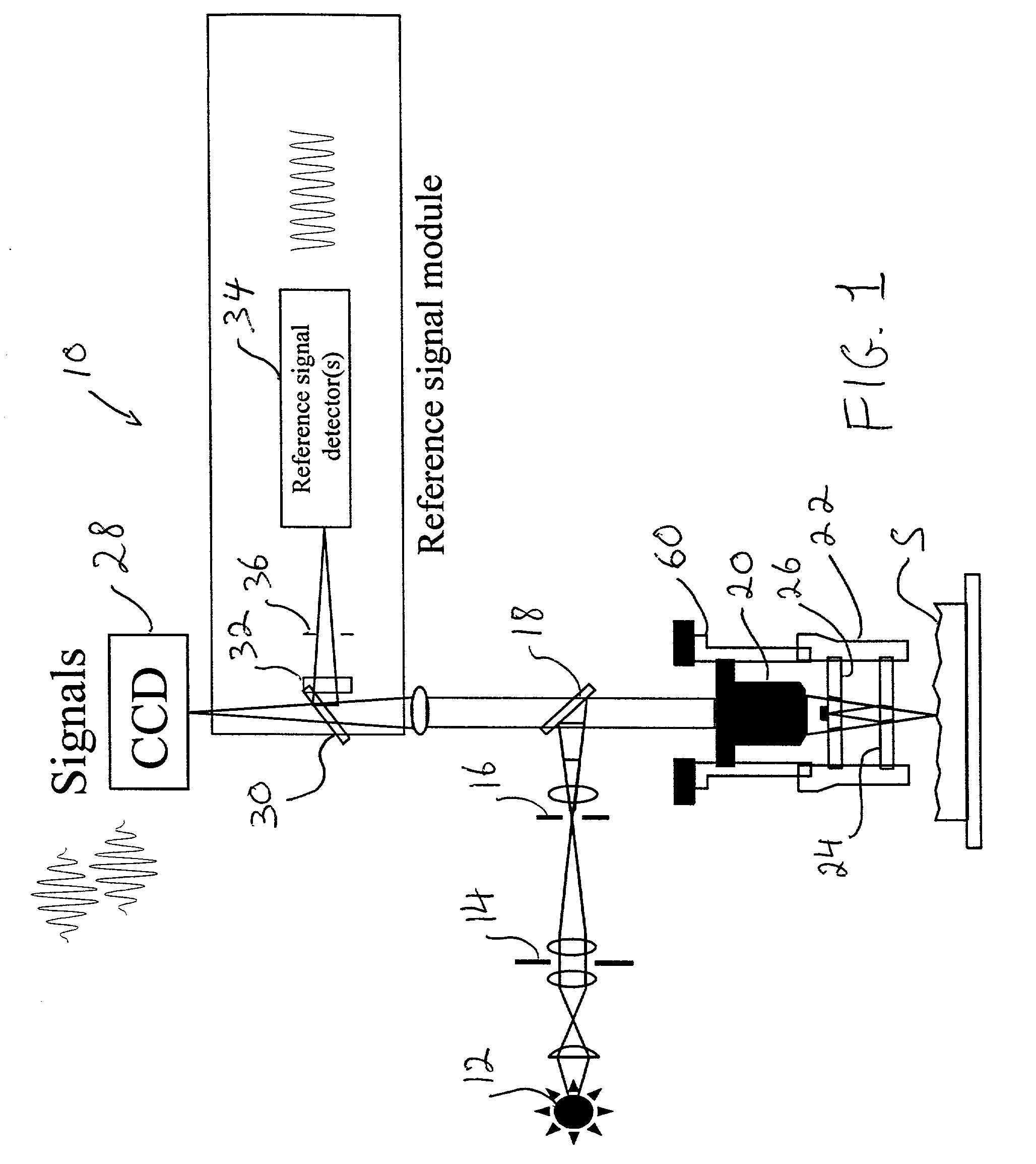
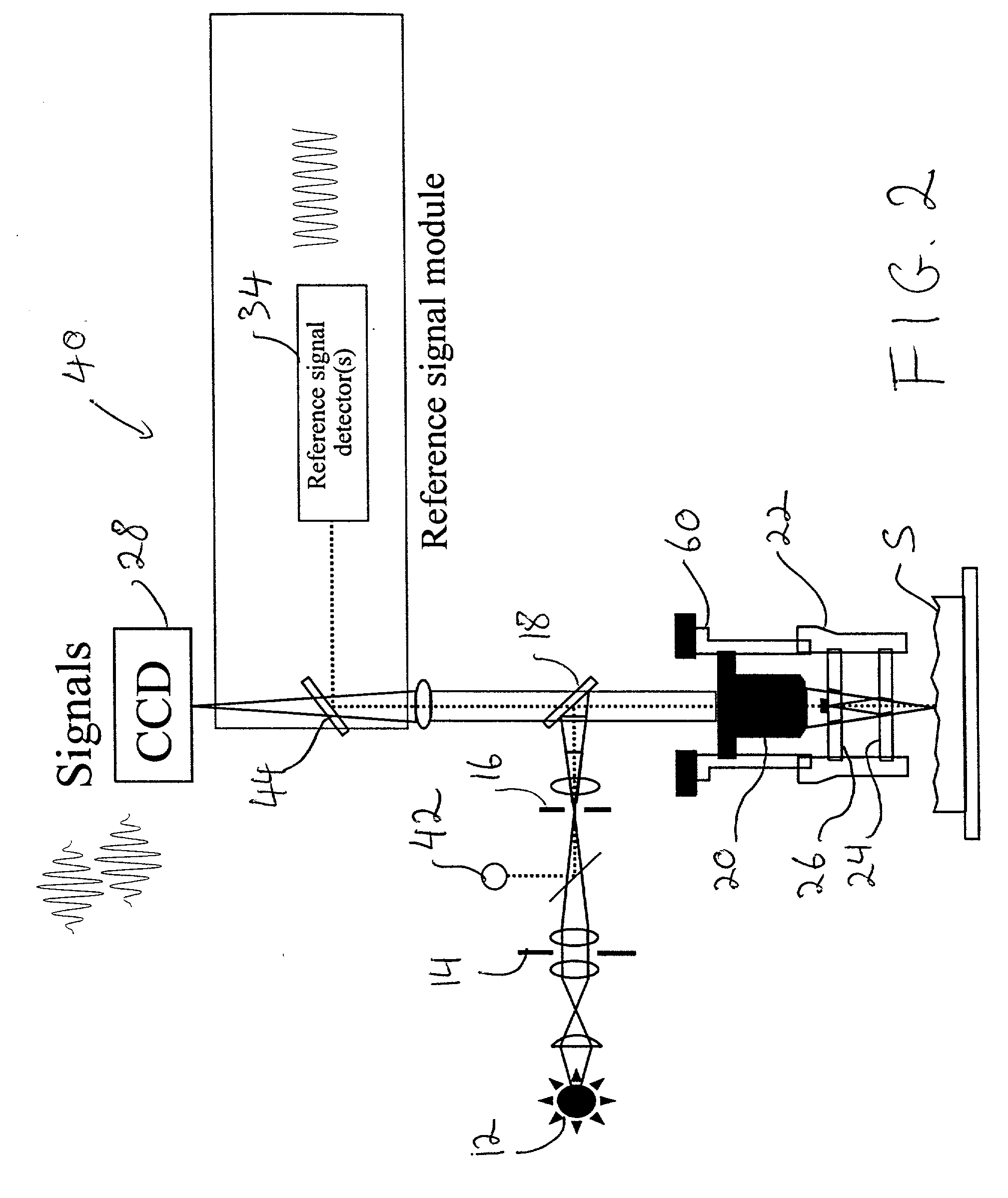
[0031] The inventive concept of this disclosure resides in the idea of using a reference signal to track the actual behavior of the scanner in an interferometer to produce scanner-position data that can be used to correct errors introduced by scanner nonlinearities and other error sources. A narrow-band light source is advantageously utilized to cover the entire range of operation of the scanner. Thus, the invention is suitable for implementation with all types of conventional interferometric techniques.

[0032] The invention is described with reference to x, y and z orthogonal coordinates wherein x and y define the plane approximately parallel to the test surface and z defines the vertical scanning direction, but it is obvious that the structure and operation of the features detailed in this specification can be rotated in any direction with equivalent results. Also, the term "correlogram" is used to refer to the three-dimensional set of interferograms produced by a multistep scan du...


PUM


Abstract

A reference signal is used to track the actual behavior of the scanner in an interferometer to produce scanner-position data that can be used to correct errors introduced by scanner nonlinearities and other error sources. A narrow-band light source is advantageously utilized to cover the entire range of operation of the scanner. Because of the independent reference channel, the invention is suitable for implementation with all types of conventional interferometric techniques. The concept is preferably implemented by utilizing an additional light source and the same scanner and detector used for the measurement, so that the OPD varies in synchronization of both the reference-signal and data-collection procedures. Alternatively, a high temporal-coherence filter may be used with the same light source and optical path used for the interferometric measurement.

Description

[0001] 1. Field of the Invention[0002] This invention is related in general to the field of scanning interferometry and, in particular, to a new approach for correcting motion nonlinearities and other scanning errors occurring during interferometric measurements.[0003] 2. Description of the Related Art[0004] Conventional scanning interferometry utilizes a light source, such as white light or a laser beam, to produce interference fringes at a light detector as the optical path difference (OPD) between a test surface and a reference surface is varied during a vertical scan. All measurement techniques based on phase shifting interferometry (PSI), vertical scanning interferometry (VSI, also referred to as white-light interferometry), combinations of VSI and PSI, phase shifting interferometry on-the-fly (PSIOTF), and lateral scanning interferometry (LSI, disclosed in Ser. No. 09 / 569,131) rely on an analysis of the interference between two beams of light. One beam (the object beam) is ref...

Claims


Application Information

Patent Timeline
26 Dec 2002
Publication
US20020196450A1
IPC
G01B9/02; G01Q30/06; G01B11/02; G01B11/24; G01Q60/00
CPC
G01B11/2441; G01J3/45; G01B2290/60; G01B9/02071; G01B9/0209; G01B9/02057
Inventors
OLSZAK, ARTUR; SCHMIT, JOANNA