[0036] Further, the covering layer 16 of the invention preferably has a thickness of 30 .mu.m or less, but 4 .mu.m or more. If the thickness exceeds 30 .mu.m, the
surface roughness of the
resultant covering layer tends to be coarsened. On the other hand, if the thickness is less than 40 .mu.m, there is a tendency that the
resultant covering layer may not act as a
barrier layer which prevents contaminants in the underlying conductive layer 14 from migrating onto the surface of the covering layer, and its
wear resistance may be decreased. Most preferably, the thickness of the covering layer 16 is about 10 .mu.m to about 20 .mu.m.
[0039] However, a fluorine-containing
polyol is particularly preferably used as the polyol in the present invention. The fluorine-containing polyol not only produces a covering layer having a larger frictional electrostatic chargeability by the reaction with the
isocyanate compound, but also reduces environmental dependency of the resistivity of the formed covering layer. The higher the fluorine content of the fluorine-containing polyol, the larger the triboeletric series in the negative side. Preferable examples of such a fluorine-containing polyol include a
copolymer made using
ethylene trifluoride monomer as a main
raw material (
copolymer polyol containing
ethylene trifluoride monomer units as the main or major component), and a
copolymer made using ethylene
tetrafluoride monomer as a main component (copolymer polyol containing ethylene
tetrafluoride monomer units as the main or major component). These fluorine-containing polyols are commercially available, e.g., under the tradename ZEFFLE from Daikin, Inc., Japan (copolymer polyol containing ethylene
tetrafluoride monomer units as the main or major component), and under the tradename LUMIFLON from Asahi Glass Industries, Japan (copolymer polyol containing trifloromonohaloethylene monomer units as the main or major component). A fluorine-containing polyol commercially available from Dainippon Ink & Chemicals, Inc., Japan, under the tradename DEFENSA may also he used. Such fluorine-containing polyols are, for example, made with ethylene tetrafluoride monomer used as a main
raw material, and contain, at least 2 moles of hydroxy monocarboxylic acid ester of
acrylic acid and / or glycol monoester of
acrylic acid, copolymerized thereto. These fluorine-containing copolymeric polyol are provided with OH components by the acrylic ester monomer noted above (i.e., OH of the carboxyl group for the hydroxy monocarboxylic acid ester of
acrylic acid, and the unesterified glycolic OH for the glycol monoester of acrylic acid). In the present invention, the copolymeric polyol containing ethylene tetrafluoride monomer as the major component is particularly preferred.
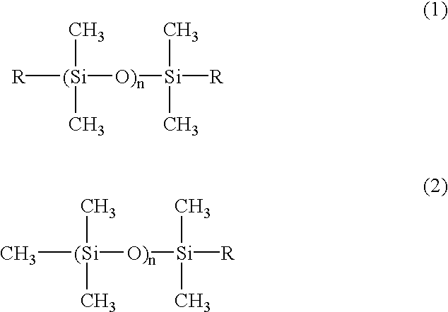
[0046] Incidentally, the present inventor has found that, while the microporous fluorine-containing
polyurethane covering layer 16, which is produced by the reaction of the
isocyanate compound with the fluorine-containing polyol as the preferred polyol, is strong in the negative chargeability due to the present of fluorine, the triboeletric series of the fluorine-containing
polyurethane microporous covering layer can be changed by allowing a reactive
silicone oil having an active
hydrogen to coexist in the
polyurethane-producing reaction, thereby incorporating components having a
siloxane linkage into the polyurethane which forms the covering layer. The reactive
silicone oil involving in the reaction with the
isocyanate compound together with the fluorine-containing polyol introduces the
siloxane component into the polyurethane formed by the reaction between the polyol and the
isocyanate compound. Siloxanes or silicones exhibit positive chargeability by themselves in the triboeletric series. If an incorporated amount thereof is larger, it is possible to increase the positive chargeability of the
resultant microporous fluorine-containing polyurethane covering layer 16. That is, the triboeletric series of the covering layer can be changed by changing the amount of the reactive
silicone oil added. In this case, the covering layer comprises, of course, a
reaction product of the polyol and the reactive silicone oil with the isocyanate compound (i.e., silicone-modified polyurethane).
[0053] In the developing roller 10 of the present invention, the covering layer 16, which provides the outermost layer of the roller is made of the porous body described above, and accordingly the surface of the roller constitutes a microscopically roughened surface by the pores. Thus, the
image force exerted on the toner is weakened as compared to the prior art developing roller in which the outermost layer is of a
smooth surface. As a result, with the developing roller of the present invention, the removal of the remaining toner carried out by the toner-supplying member is more facilitated, and fresh toner can be more readily adhered to the outermost layer. Therefore, with the developing roller of the present invention, the negative ghost, which is caused by the toner remaining on the developing roller, is far more suppressed as compared to the prior art developing roller having a
smooth surface. Further, the covering layer constituting the outermost layer of the developing roller of the invention is porous, and thus is elastic and readily deformable in response to an external force. In addition, the covering layer of the invention forms a film far softer than the toner, does not damage the toner at, for example, the nip portion with the photosenisitive drum.

