
Gas-storage power plant

Inactive Publication Date: 2003-02-20
GENERAL ELECTRIC TECH GMBH
View PDF0 Cites 24 Cited by
  • Summary
  • Abstract
  • Description
  • Claims
  • Application Information

AI Technical Summary

Benefits of technology

[0005] The invention is intended to provide a remedy here. The object of the present invention is to show a gas-storage power plant of the type mentioned at the beginning which ensures relatively high reliability and operating safety for the valve arrangement.
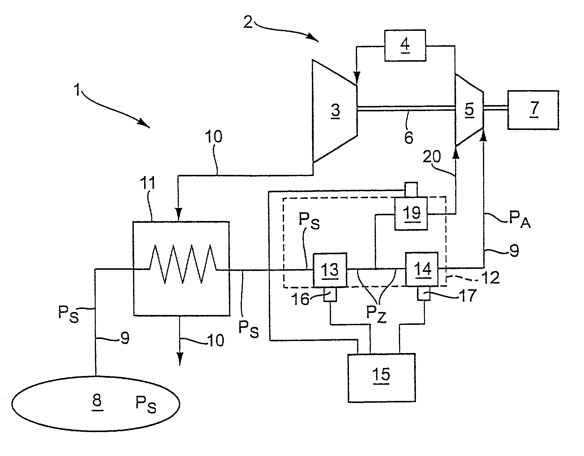
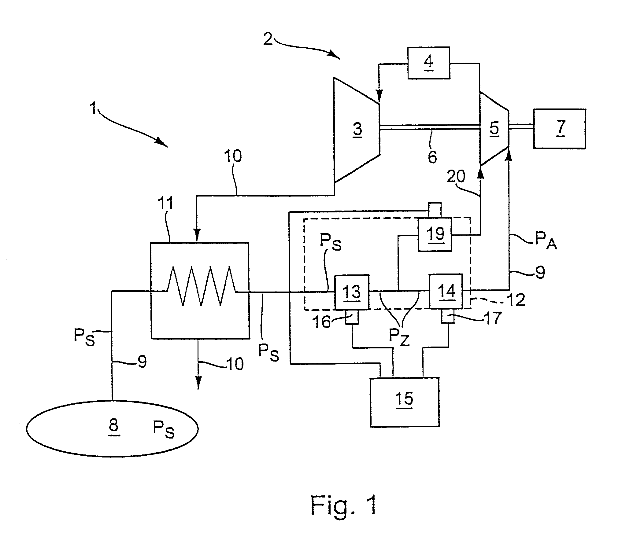
[0007] The present invention is based on the general idea of designing the throttling of the storage pressure to the working pressure in at least two stages. This measure leads to considerably smaller pressure differences in the individual throttling stages. Accordingly, the loading on the throttling points is reduced. Furthermore, the invention provides considerable simplification of the closed-loop or open-loop control of the individual throttling points by the first throttling stage being controlled in a closed-loop or open-loop system according to the changes in the storage pressure, whereas the last throttling stage is controlled in a closed-loop system according to the changes in the working pressure or the intermediate pressure. Both the reduction in the outlay for the closed-loop or open-loop control of the throttling points and the reduction in the pressure difference occurring at the individual throttling points result in an increase in the reliability and the operating safety of the valve arrangement.
[0009] The first throttling stage serves to reduce the storage pressure applied on the inlet side to an intermediate pressure. The result of this measure is that the aforesaid intermediate pressure is admitted on the inlet side to the second throttling point, a second control valve, as a result of which the throttling to the working pressure is considerably simplified.
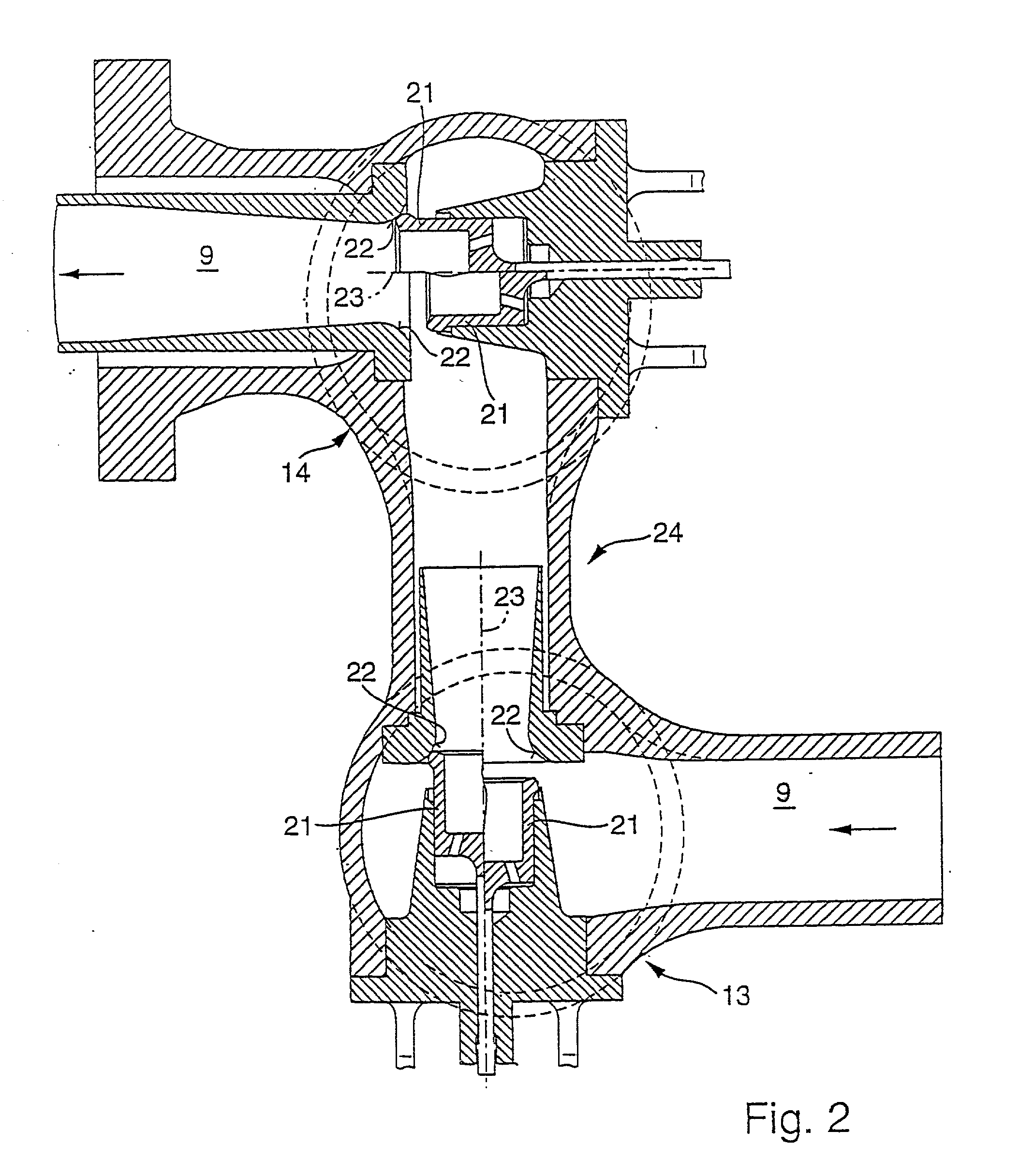
[0012] In a further embodiment, a control valve or a plurality of control valves are designed as relieved single-seat valves. All the control valves are preferably designed as relieved single-seat valves, which permits a cost reduction. A relieved single-seat valve has the advantage that it requires small actuating forces and thus small drives. Small drives also have short actuating times. (Such short actuating times ensure that the overspeed of the air turbine in the event of a blackout remains within the required limits.)
[0029] According to FIG. 2, the two control valves 13 and 14 can be combined in a common housing to form a subassembly 24, which makes it simpler to fit them into the gas-supply lines 9. In addition, the bypass valve 19 (cf. FIG. 1) can be integrated in this subassembly 24 between the control valves 13 and 14. As can be seen from FIG. 2, the two control valves 13 and 14 may expediently be of the same construction having identical or similar components. In this way, the multiplicity of parts can be reduced on the one hand and the component parts cost can be reduced on the other hand due to larger batch quantities. The two control valves 13 and 14 may differ from one another, for example, in their flow cross sections.
[0034] The valve arrangement 12 in the case of the invention therefore only needs two feedback control circuits of simple construction. The outlay for the closed-loop or open-loop control of the valve arrangement 12 is reduced by this construction. Furthermore, increased operating safety and reliability is obtained at the same time, which is due to the reduced stress on the valves. In addition, the result of the two-stage throttling is that the maximum pressure differences applied separately at the control valves 13 and 14 are markedly smaller than the pressure difference between storage pressure P.sub.S and working pressure P.sub.A, a factor which reduces the stress on the control valves 13 and 14. In particular, vibrations, oscillation excitations and noise generation can be reduced or completely avoided.

Problems solved by technology

However, increased outlay in terms of closed-loop or open-loop control at the control valve may be at the expense of the reliability and thus of the operating safety of the control valve arrangement.
Furthermore, in particular during start-up and during the loading of the turbogroup, very high pressure differences may be present between the storage pressure applied at the inlet side of the control valve and the working pressure to be provided on the outlet side, for example if the gas reservoir is still filled to the maximum level and the turbogroup only requires a minimum working pressure.
In the process, vibrations and oscillation excitations, in particular in combination with noise emissions, may occur in the control valve, as a result of which the control valve is highly loaded.
High loads may lead to material fatigue and to failure.
A control valve which fails during start-up of the turbines may lead to damage or destruction of the turbines.

Method used


Image

  • Gas-storage power plant
  • Gas-storage power plant
  • Gas-storage power plant

Examples


Embodiment Construction

[0005] The invention is intended to provide a remedy here. The object of the present invention is to show a gas-storage power plant of the type mentioned at the beginning which ensures relatively high reliability and operating safety for the valve arrangement.

[0006] This problem is solved by the subject matter of the independent claims. Advantageous embodiments are the subject matter of the dependent claims.

[0007] The present invention is based on the general idea of designing the throttling of the storage pressure to the working pressure in at least two stages. This measure leads to considerably smaller pressure differences in the individual throttling stages. Accordingly, the loading on the throttling points is reduced. Furthermore, the invention provides considerable simplification of the closed-loop or open-loop control of the individual throttling points by the first throttling stage being controlled in a closed-loop or open-loop system according to the changes in the storage p...


PUM


Abstract

The present invention relates to a gas-storage power plant, comprising a gas reservoir (8) in which a gas can be stored under pressure, a turbogroup (2) which has at least one turbine (3, 5), a gas-supply line (9) which leads from the gas reservoir (8) to the turbogroup (2), and a valve arrangement (12) which is arranged in the gas-supply line (9) and throttles a storage pressure (PS) applied on the inlet side to a working pressure (PA) by closed-loop and / or open-loop control. In order to improve the reliability of the valve arrangement (12), it has at least two control valves (13, 14) arranged in series. A leading first control valve (13) throttles the storage pressure (PS) applied on the inlet side to an intermediate pressure (PZ) by closed-loop or open-loop control. A subsequent second control valve (14) throttles the pressure (PZ) applied on the inlet side to the working pressure (PA) by closed-loop control.

Description

[0001] The invention relates to a gas-storage power plant having the features of the preamble of claim 1. The invention also relates to a method of throttling a storage pressure to a working pressure for a turbogroup of such a gas-storage power plant.PRIOR ART[0002] Such a gas-storage power plant is normally interconnected in a "Compressed-Air-Energy-Storage System", in short a CAES system. The basic idea of a CAES system is seen in the fact that excess energy which is generated by permanently operated conventional power generating plants during the base-load times is transferred to the peak-load times by bringing gas-storage power plants onto load in order to thereby use up less resources overall for producing electrical energy. This is achieved by air or another gas being pumped under a relatively high pressure into a reservoir by means of the inexpensive excess energy, from which reservoir the air or gas can be extracted when required for generating relatively expensive current. ...

Claims


Application Information

Patent Timeline
IPC IPC(8): F02C6/16
CPCF02C6/16Y02E60/15Y02E60/16Y10T137/87917
Inventor KONEZCINY, STEPHANSUTER, FRANZ
Owner GENERAL ELECTRIC TECH GMBH
Learn More