Electrical machine

a technology of electric machines and motors, applied in the direction of machines/engines, mechanical equipment, magnetic circuit shapes/forms/construction, etc., can solve the problems of limited life and wear of the commutator

Inactive Publication Date: 2003-03-13
VOLVO TECH
View PDF10 Cites 11 Cited by
  • Summary
  • Abstract
  • Description
  • Claims
  • Application Information

AI Technical Summary

Problems solved by technology

Such a commutator is subjected to

Method used


Image

  • Electrical machine
  • Electrical machine
  • Electrical machine

Examples


first embodiment

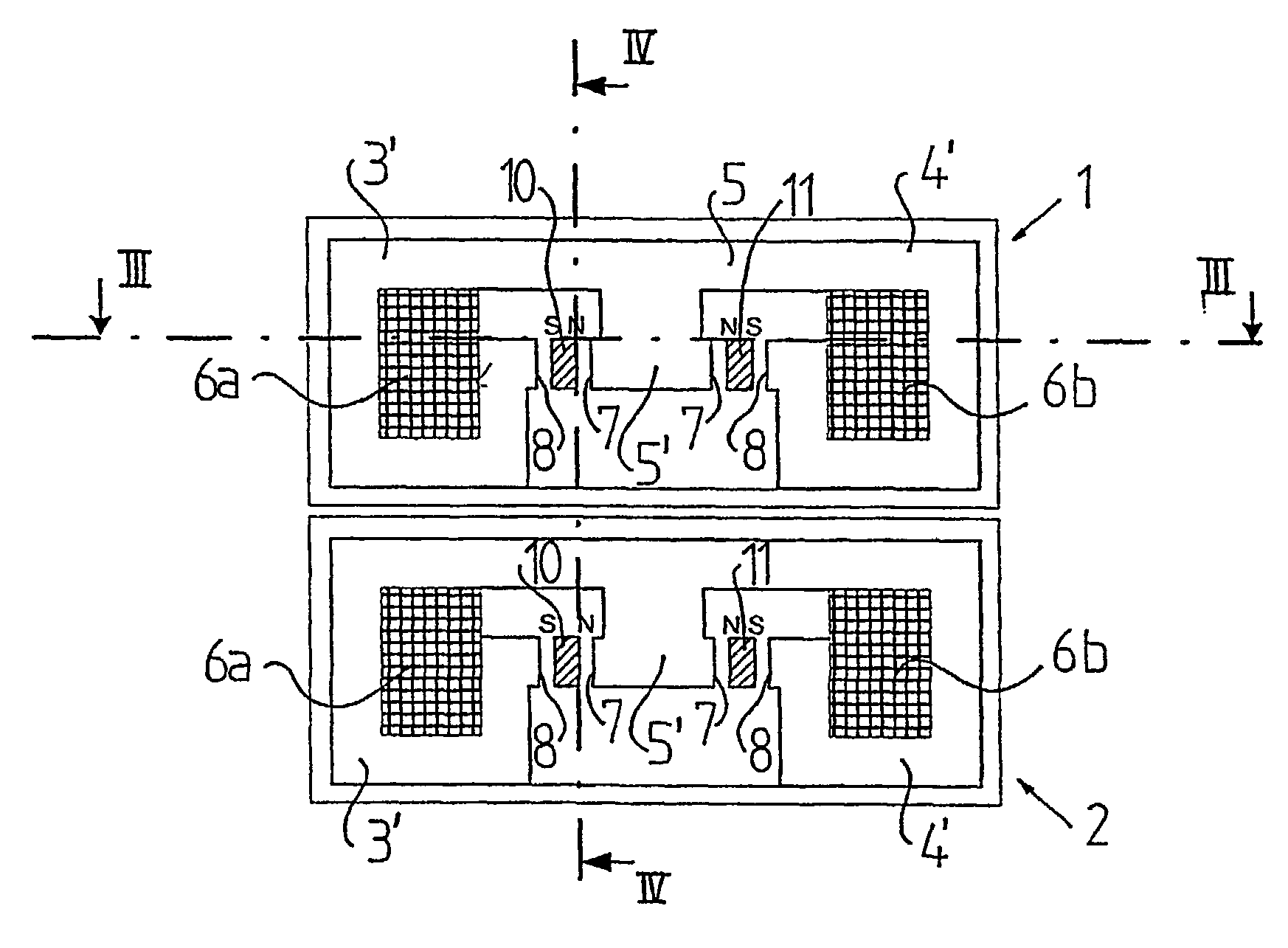
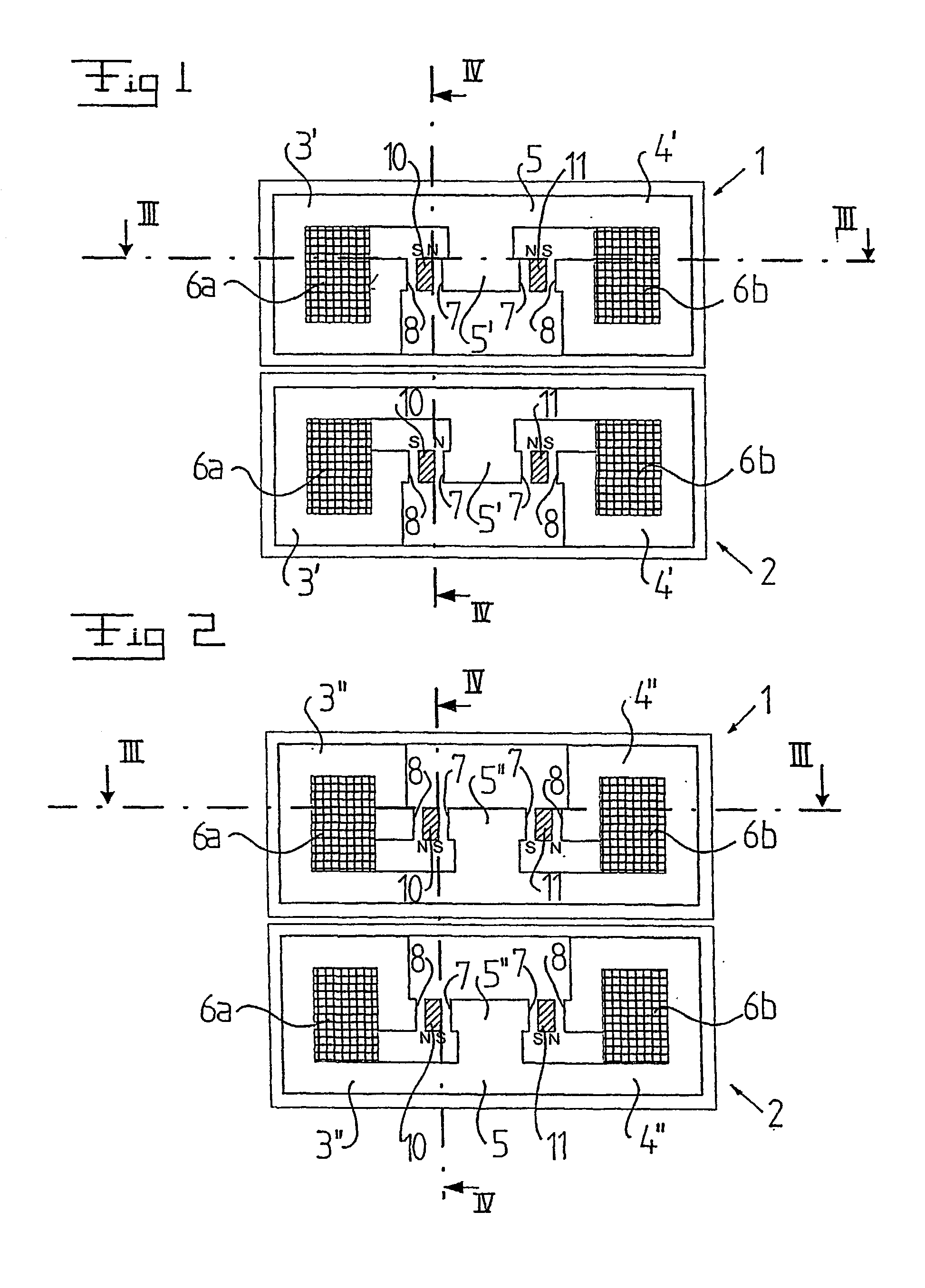
[0043] With reference to FIGS. 1-4, an electrical machine with a first machine unit 1 and a second machine unit 2 is disclosed. The machine units 1 and 2 have a substantially identical design and we will therefore only describe the first machine unit 1 more closely.

[0044] The first machine unit 1 includes a stator, which includes a plurality of magnetic flux conductors 3', 3", 4', 4". The first machine unit 1 also includes an electric conductor forming a winding 6a, 6b, 6c, 6d, which may consist of one or several coils. The winding 6a, 6b, 6c, 6d forms a substantially closed path, which extends through each magnetic flux conductor 3', 3", 4', 4". The closed winding path forms an elongated ring having a first current carrying portion 6a and a second current carrying portion 6b. The first current carrying portion 6a extends through the magnetic flux conductors 3' and 3", and a second current carrying portion 6b extends through the magnetic flux conductors 4' and 4". The two current ca...

fourth embodiment

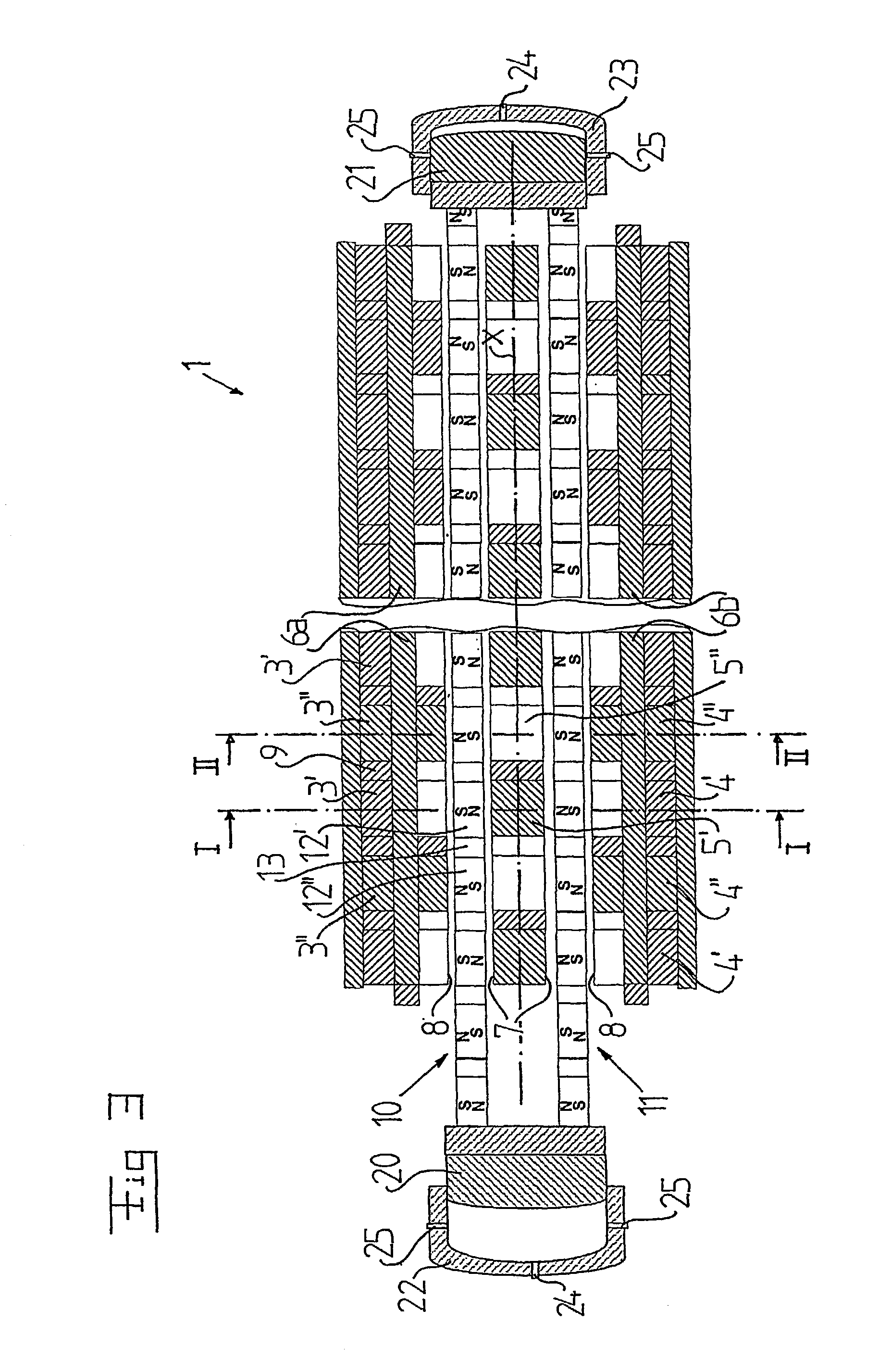
[0059] FIGS. 8 and 9 discloses a fourth embodiment, which differs from the previous embodiments by the fact that the windings 6a, 6b are completely located beside the movable elements 10 and 11. In such a way, the connecting portions 6c and 6d do not need to be bended outwardly in the manner disclosed in FIG. 4.

fifth embodiment

[0060] FIGS. 10 and 11 discloses the invention, which differs from the previous embodiments by the fact that the permanent magnet elements 12', 12" are inclined in relation to the direction of the magnetic flux approaching the permanent magnet element and leaving the same. In this embodiment, the movable elements 10 and 11 include magnetic flux conductors 31, 32 for conducting the magnetic flux through the movable element 10, 11 to and from the permanent magnet elements 12', 12". In the embodiment disclosed, all permanent magnet elements 12', 12" are inclined in the same direction. It is also possible to let the permanent magnet elements 12', 12" of one of the elements 10 be inclined in a first direction and the permanent magnet elements 12', 12" of the other element 11 in another direction extending substantially 90.degree. in relation to the first direction.

[0061] FIGS. 12 and 13 discloses a sixth embodiment of the invention similar to the fifth embodiment, but where the magnet po...


PUM


Abstract

The invention refers to an electrical machine with at least a machine unit (1). This machine unit includes a stator, which includes a plurality of magnetic flux conductors (3', 3'') and an electric conductor forming a winding extending in a substantially closed winding path through each magnetic flux conductor, and at least one first movable element (10), which includes a number of permanent magnet elements (12', 12'') and which is movable in a reciprocating movement in relation to the stator along a first movement path in a space having a finite length and formed by at least some of said magnetic flux conductors. The winding path includes a first current carrying portion (6a), which extends substantially in parallel with the first movement path. Each magnetic flux conductor (3', 3'') is arranged to form, together with one of said permanent magnet elements (12', 12''), a closed magnetic flux circuit extending around said current carrying portion.

Description

THE BACKGROUND OF THE INVENTION AND PRIOR ART[0001] The present invention refers to an electrical machine including a stator, which has magnetic flux conductors and a winding extending through said magnetic flux conductors, and at least one movable element, which is movable in relation to the stator.[0002] Linear electrical machines are known in various connections, for instance as free-piston engines, i.e. an engine with a piston, which is mechanically freely movable in a cylinder housing. Consequently, there is no mechanical element, such as a connecting rod or a crank shaft, for the transfer of energy from the piston, but the kinetic energy of the piston is transformed directly to electrical energy by means of the linear electrical machine. Such a linear generator could, for instance, include a magnetic element in the piston and an electromagnetic element in the wall of the cylinder housing.[0003] U.S. Pat. No. 5,788,003 discloses such a combustion engine of a free-piston type fo...

Claims


Application Information

Patent Timeline
IPC IPC(8): F02B1/12F02B71/04H02K7/18H02K35/02H02K41/03
CPCF02B1/12F02B63/041F02B71/04H02K57/003H02K7/1884H02K35/02H02K41/031H02K1/14H02K99/10
Inventor SADARANGANI, CHANDURGERTMAR, LARSARSHAD, WAQAS
Owner VOLVO TECH
Why Eureka
Try Eureka