Method and apparatus for measuring fill level in bottles

a technology for measuring the level of filling and bottles, applied in liquid handling, instruments, machines/engines, etc., can solve the problems of adding to the cost and complexity of the inspection system, and achieve the effects of reducing the number of improperly filled bottles, avoiding inaccurate measurements, and preventing oxidation

Inactive Publication Date: 2003-03-20
INDAL DYNAMICS
View PDF0 Cites 15 Cited by
  • Summary
  • Abstract
  • Description
  • Claims
  • Application Information

AI Technical Summary

Benefits of technology

[0008] The present invention provides method and apparatus for measuring the liquid fill level in bottles while the bottles are still within the turret section of the filler system. Measuring the bottles for fill level while they are in the filler turret enables the exact valve number that fills each bottle to be known without complex memory systems tracking the bottle downstream of the filler station to the reject station. As stated hereinabove, in the carbonated beverage industry, the bottles are usually "foamed over" before the capper station to purge any oxygen in the headspace above the liquid to prevent oxidation of their content which can change the true fill point in the bottles. The present invention avoids inaccurate measurements downstream of the capper station by measuring the fill level prior to capping. Further, the newer beverage filler systems have electronic controlled valves that are adjusted, or tuned, to provide the desired bottle fill level. In accordance with the teaching of the present invention, the exact liquid level, as measured by the system optics, is used as a signal for the electronics that control the filler valves enabling the operator to set the desired fill level in the bottles and detect faulty or malfunctioning valves at the early stages of the filling process, thus reducing the number of improperly filled bottles that must be discarded and, in turn, reducing process costs.

Problems solved by technology

Inspecting fill levels after capping and providing the support mechanism for doing so adds to the cost and complexity of the inspection system.

Method used


Image

  • Method and apparatus for measuring fill level in bottles
  • Method and apparatus for measuring fill level in bottles
  • Method and apparatus for measuring fill level in bottles

Examples


Embodiment Construction

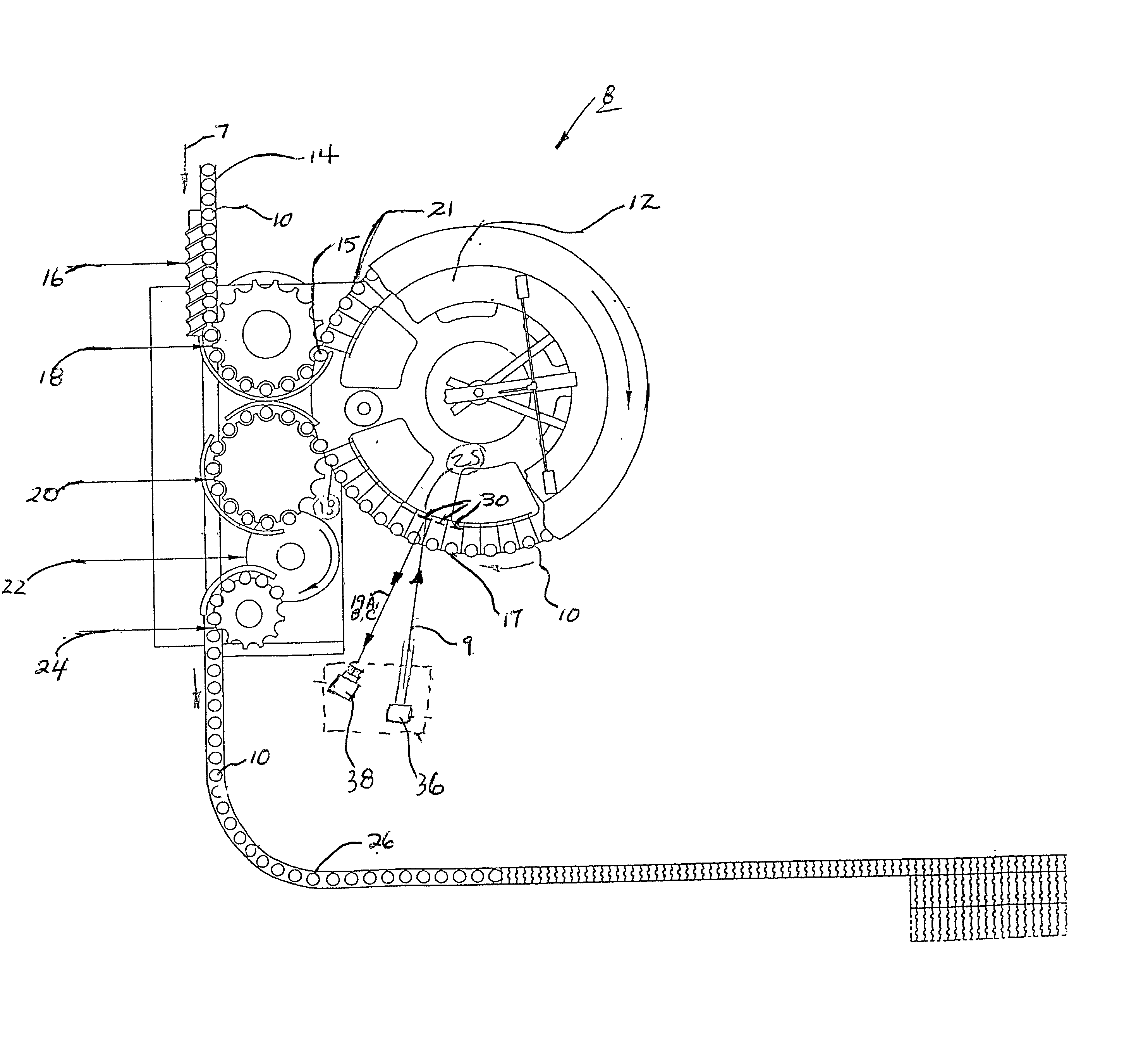
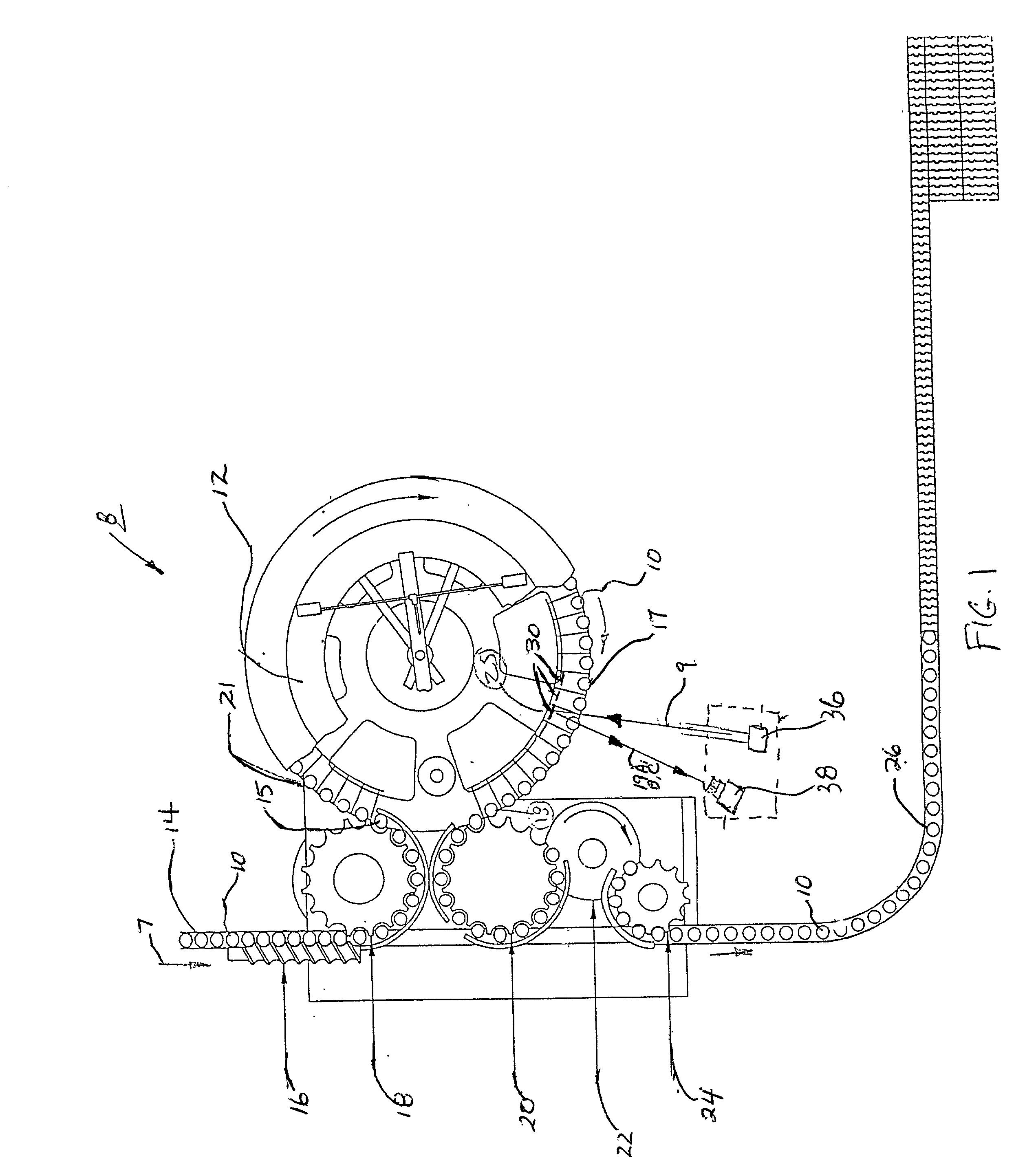
[0014] Referring now to FIG. 1, a top view of a conventional beverage filler system 8 used to fill and measure, or inspect, cola, beer and water bottles is illustrated. The bottles 10 are fed into the rotating filler turret 12 by means of a chain type conveyor 14 moving in the direction of arrow 7. A timing screw 16 spaces the bottles 10 into the infeed starwheel 18 which then places the bottles 10 into the rotating filler turret 12. As the bottles 10 travel around the turret 12, they are filled with the beverage and then placed into the transition starwheel 20 which hands them off to capper 22. Bottles 10 are fed from capper 22 into the outfeed starwheel 24 which deposits them on the outfeed conveyor 26. The bottles are precisely indexed from the infeed starwheel 18 through the filler turret 12, transition starwheel 20, capper 22 and into the outfeed starwheel 24. Precise indexing is required since the filler system 8 operates at a high rate of speed ( up to 1200 bottles per minute...


PUM

PropertyMeasurementUnit
liquid levelaaaaaaaaaa
liquid fill levelaaaaaaaaaa
transparentaaaaaaaaaa

Abstract

Method and apparatus for measuring the liquid fill level in bottles while the bottles are still within the turret section of the filler system. A source of focused light, such as that generated by a laser, is directed onto a series of targets positioned on the turret behind the bottles. The beam is directed back through the bottle neck and detected by a remote camera. The detected image varies depending upon whether the bottle was underfi

Description

[0001] 1. Field of the Invention[0002] The present invention provides method and apparatus for measuring the fill level in containers, such as transparent bottles and jars, while the bottles are still within the filler turret section of the filler apparatus.[0003] 2. Description of the Prior Art[0004] Systems for measuring the fill level in bottles have been commercially available for many years. In most modern beverage fillers, the bottles from the infeed starwheel are placed on a bottom stirrup in the filler rotary turret. Each of the stirrups are movable in the vertical direction and are lifted by a mechanism, such as a cam, so that the top of each bottle is engaged into a filling cup. This cup seals the internal volume of the bottle from normal atmospheric conditions. A vacuum is usually applied to each bottle and the filler then allows the beverage to flow into the bottle. By first applying the vacuum, the bottles may be filled faster and minimizes foaming in carbonated beverag...

Claims


Application Information

Patent Timeline
Patent Type & Authority Applications(United States)
IPC IPC(8): B67C3/00B67C3/28G01F23/292
CPCB67C3/007B67C3/284G01F23/292
Inventor CALHOUN, FRED L.
Owner INDAL DYNAMICS
Why Eureka
Try Eureka