Fluorescence endoscope apparatus and method for imaging tissue within a body using the same

a fluorescence endoscope and tissue technology, applied in the direction of fluorescence/phosphorescence, instruments, catheters, etc., can solve the problems of low efficiency, fluorescence endoscope system, and inability to provide high-definition video images

Inactive Publication Date: 2003-04-24
MEDIMIR
View PDF10 Cites 139 Cited by
  • Summary
  • Abstract
  • Description
  • Claims
  • Application Information

AI Technical Summary

Problems solved by technology

Such examination process has problems of expanding examination time of a patient, and a doctor, as a user, loses a chance to compare images obtained from fluorescence light and reflective light on the same region, which in turn causes an effectiveness reduction.
However, it was known that the fluorescence endoscope system introduced in the U.S. Pat. No. 4,821,117 does not provide high definition video images.
However, since the required high sensitivity level is to be reached in monochrome television systems due to amplification of image intensifiers or use of a mode of signal accumulation the fluorescence endoscope of the U.S. Pat. No. 4,821,117, which processes images received from the reflected illumination light and the fluorescence light produced by the excitation light through a television camera, has a problem of not providing high definition video images.
Also, the cyclic filming process for an image recording uses unnecessary fluorescence light energy during non-examining hours because of the excitation light.
Moreover, the system is com

Method used


Image

  • Fluorescence endoscope apparatus and method for imaging tissue within a body using the same
  • Fluorescence endoscope apparatus and method for imaging tissue within a body using the same
  • Fluorescence endoscope apparatus and method for imaging tissue within a body using the same

Examples


Embodiment Construction

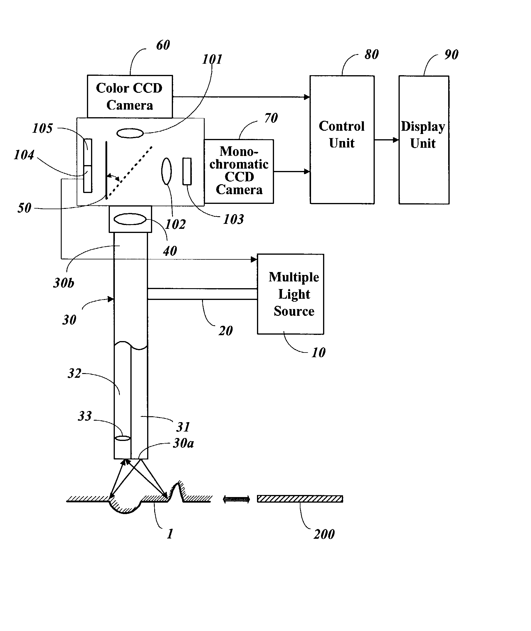
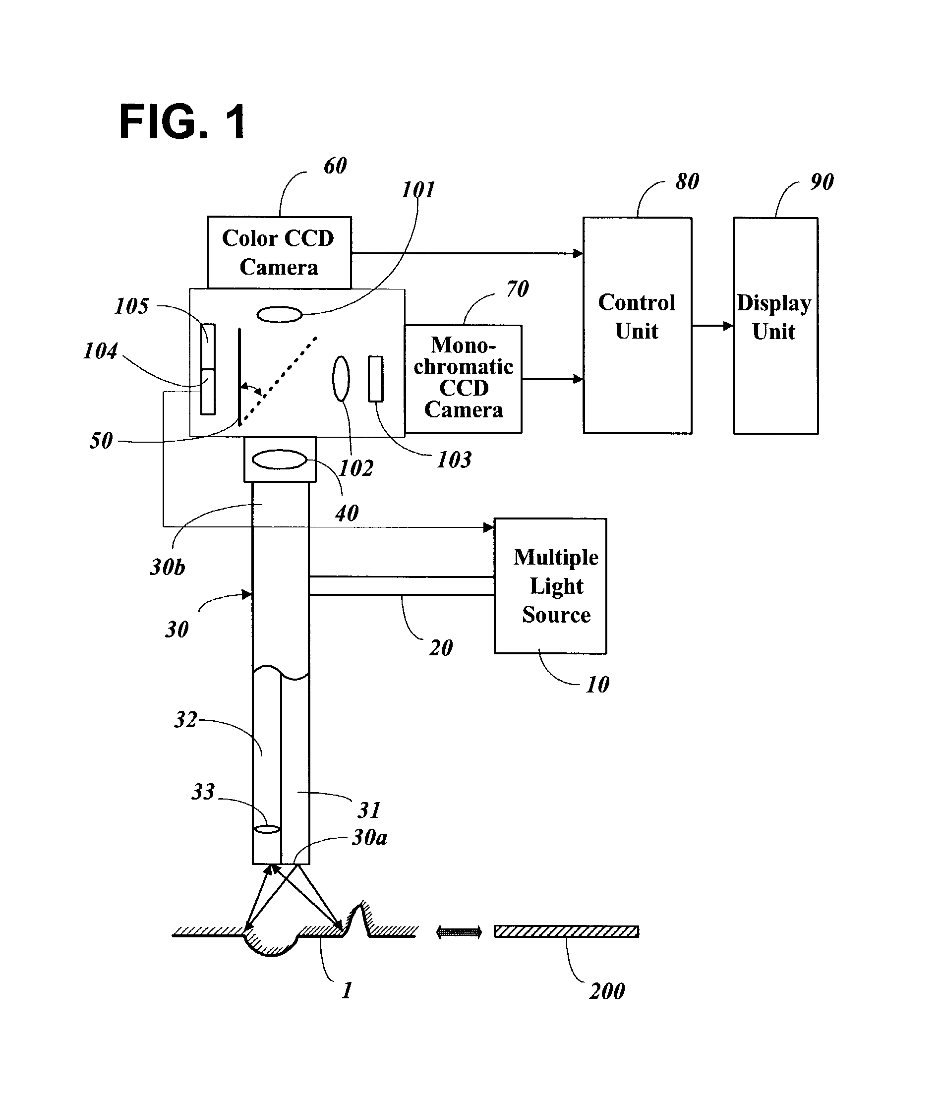
[0016] In order to facilitate an understanding of this invention, a fluorescence endoscope apparatus, an apparatus for examining tissue within a body, is comprised of, a multiple light source unit, equipped with multiple light sources of different wavelengths, to provide a selected light; a light transmission unit with an objective lens installed on the incidence path to make an insertion into a body possible, where the exit path, for transmitting and radiating the provided light, and the incidence path, for transmitting the incidence light in correspondence with the radiation, are formed in parallel; an light splitting unit for splitting the light transmitted via the incidence path into primary light and secondary light; a primary image processing unit for collecting primary images based on the primary light that has passed through; a secondary image processing unit for collecting secondary images based on the secondary light that has been reflected; a control unit for processing, ...


PUM


Abstract

This present invention relates to a fluorescence endoscope apparatus, developed for diagnosing various illnesses within a body, especially for diagnosing a tumor inflamed region; and an application method of the same. The purpose of this invention is to enhance the accuracy of the examination. The fluorescence light endoscope apparatus in accordance with the present invention is comprised of an endoscope probe; a multiple light source that provides illumination light or excitation light of short wavelength onto a diagnostic region; a color CCD camera and a high sensitive monochromatic CCD camera placed on the back of an endoscope ocular lens; a reference test sample; a computer; and a monitor. The method of the present invention embodies a preliminary correction of the fluorescence endoscope apparatus of the present invention in accordance with the reference test sample; a general endoscopy using the illumination light, and an image observation and examination of the same diagnostic region using the fluorescence light and the reflected excitation light simultaneously; an auto-correction of brightness and unevenness of the fluorescence light images of the diagnostic region according to the reference test sample data; an evaluation of the brightness of the fluorescence light in the diagnosis region; storing numerical data that characterizing images and brightness of the fluorescence light in the diagnosis region; and storing image collected via two cameras as digital video clips.

Description

[0001] 1. Field of the Invention[0002] The present invention relates to a fluorescence endoscope apparatus and a method for imaging tissue within a body cavity using the same, and in particular to a fluorescence endoscope apparatus and a method for examining tumor within a body.[0003] 2. Description of the Related Art[0004] In general, existing general endoscopes are categorized into a fiber optical endoscope, which uses optical fibers and an optical lens; and an electron microscope that uses optical fibers for projecting light and has a receiver that converts image signals into electronic signals through a CCD micro chip mounted at the distal end of an endoscope probe which can be observed through a monitor. On the other hand, the fiber optical endoscope can also use a monitor for an observation, in this case the observation through a monitor can be done after converting image signals into electronic signals through a CCD camera installed on the back of an ocular lens of the same.[...

Claims


Application Information

Patent Timeline
IPC IPC(8): A61B1/00A61B1/04G01N21/64A61B5/00A61B17/00G02B23/26H04N7/18
CPCA61B1/042A61B1/043A61B2017/00061A61B5/0084A61B5/0071
Inventor KANG, UKPAPAYAN, GARRY V.
Owner MEDIMIR
Why Eureka
Try Eureka