Eureka AIR delivers breakthrough ideas for toughest innovation challenges, trusted by R&D personnel around the world.

Scroll compressor

Inactive Publication Date: 2003-05-01
MITSUBISHI ELECTRIC CORP
View PDF0 Cites 5 Cited by
  • Summary
  • Abstract
  • Description
  • Claims
  • Application Information

AI Technical Summary

Benefits of technology

[0090] According to one aspect of the scroll compressor of the present invention, the rotation prevention structure which regulates a rotation of the compliant frame by being interlocked with the reamer pin inserted in the guide frame is composed of combination of the reamer pin and the reamer holes, and the diameter clearance of the reamer pin and the reamer hole at the contact part is set to be larger than the maximum diameter clearance at the upper or the lower fitting surface of the compliant frame and the guide frame. Therefore, it is possible to avoid the problems that the state of the reamer pin supporting all the gas compression load during operation occurs, an excessive force is loaded on the reamer pin and the reamer holes, which causes a wear increase, or that performance is fallen and noise is increased because the action of the orbiting scroll becomes unstable because of the movement of the contact point of the fitting surface of the compliant frame becoming discontinuous. Thus, the scroll compressor of high performance and high reliability can be obtained.
[0112] In a scroll compressor according to one aspect of the present invention, the first space at the first contact part where the first fitting surface of the guide frame contacts with the first fitting surface of the compliant frame is set to be shorter than the second space at the second contact part located closer to the motor than the first contact part, where the second fitting surface of the guide frame contacts with the second fitting surface of the compliant frame. Thus, a scroll compressor, in which high performance can be retained without making an excessive contact force of the spiral blade and which is easy to be mass-produced, can be obtained.
[0092] According to one aspect of the scroll compressor of the present invention, the rotation prevention structure of the compliant frame is composed of combination of a pair of a reamer pin and reamer holes, the discontinuous movement of the contact point in the radial direction of the reamer pin and the reamer hole can be minimized. Therefore, the scroll compressor of high performance and low noise where the action of the compliant frame is stabilized can be obtained.
[0110] A scroll compressor according to one aspect of the present invention further includes an orbiting axial part provided on the main shaft and an orbiting bearing provided on the orbiting scroll which transmits rotation to the orbiting axial part of the main shaft,
[0105] a compliant frame provided in the hermetic container, having a thrust bearing for supporting the orbiting scroll in the axial direction, a main bearing for supporting the main shaft in the radial direction, and two contact surfaces which independently exist, that is a first fitting surface and a second fitting surface, on an external circumference of the compliant frame,
[0111] wherein the orbiting axial part of the main shaft has its center off from the center of the main shaft, and an eccentric amount which is a distance between the center of the orbiting axial part and the center of the main shaft is set to be greater than an orbiting radius specified by forms of the spiral blade of the fixed scroll and the orbiting scroll, and set to be within a range not exceeding a half of a sum of three clearances of a diameter clearance of the orbiting bearing, a diameter clearance of the main bearing, and a minimum diameter clearance at the contact surface of the compliant frame and the guide frame. Thus, a scroll compressor which can retain high quality and high performance in mass-production can be obtained.
[0112] In a scroll compressor according to one aspect of the present invention, the first space at the first contact part where the first fitting surface of the guide frame contacts with the first fitting surface of the compliant frame is set to be shorter than the second space at the second contact part located closer to the motor than the first contact part, where the second fitting surface of the guide frame contacts with the second fitting surface of the compliant frame. Thus, a scroll compressor, in which high performance can be retained without making an excessive contact force of the spiral blade and which is easy to be mass-produced, can be obtained.
[0105] a compliant frame provided in the hermetic container, having a thrust bearing for supporting the orbiting scroll in the axial direction, a main bearing for supporting the main shaft in the radial direction, and two contact surfaces which independently exist, that is a first fitting surface and a second fitting surface, on an external circumference of the compliant frame,

Problems solved by technology

As the swirl of the orbiting scroll makes the side space extend with respect to the swirl of the fixed scroll, a leak from the swirl side in the scroll compression chamber is increased, which causes performance deterioration.
Further, as the compliant frame 3 moves depending upon the space, the axis of the rotor interlocked with the main shaft also moves, which causes a contact problem of the external diameter of the rotor with the internal diameter of the stator.
Though the clearances between the compliant frame and the guide frame at the upper and lower fitting surfaces are set up to be almost equal, it is difficult to make the clearances at the upper and lower completely equal in every scroll compressor made in mass production.
In some cases, the compliant frame contacts the guide frame at either the upper fitting surface or the lower fitting surface and does not contact at the other surface during operation, which causes a change of vibrations of the axial system and a change of noises of the axial system, a performance fall based on increasing of the contact of the spiral blade top, and an increase of wear of the contact part at the blade top.
However, when the compliant frame 3 itself performs a rotational movement to the guide frame, there is a problem that a loss friction is generated at the part where the compliant frame 3 contacts with the upper and lower fitting surfaces 5a and 5b of the guide frame 5 and wear is also generated.
Further, there is a problem that thickness of oil film of the main bearing is reduced and a load faculty of the bearing is also decreased because the relative rotation rate of the main bearing of the compliant frame and the main shaft falls.
However, as a clearance between a diameter of the reamer pin and a diameter of the reamer hole is small, the state occurs that only the reamer pin receives a gas compression load during operation, which causes a problem of a smooth minute orbiting motion being impeded within the guide frame of the compliant frame and wear of the reamer pin and the reamer hole being increased.
Furthermore, when the rotation prevention mechanism composed of a plurality of combinations of a reamer pin and a reamer hole is used, the number of moving times of discontinuous contact points increases during one rotation, which causes a problem of the increase in noise.
Therefore, it has a problem that wear of both the reamer pin and the reamer hole is increased.

Method used


Image

  • Scroll compressor
  • Scroll compressor
  • Scroll compressor

Examples


embodiment 1

[0060]

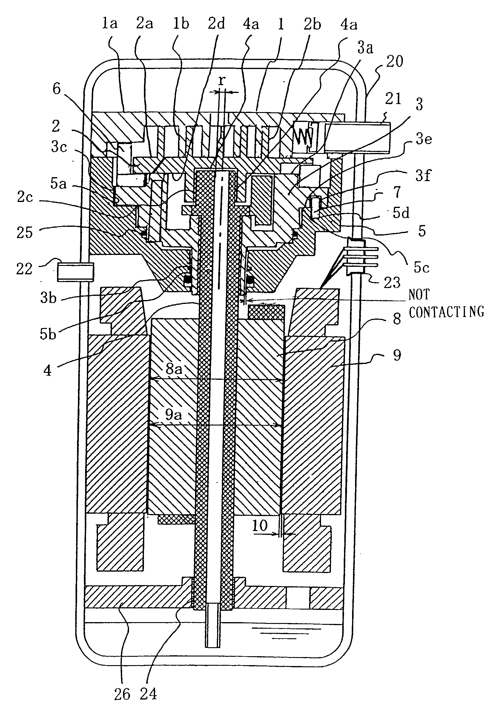
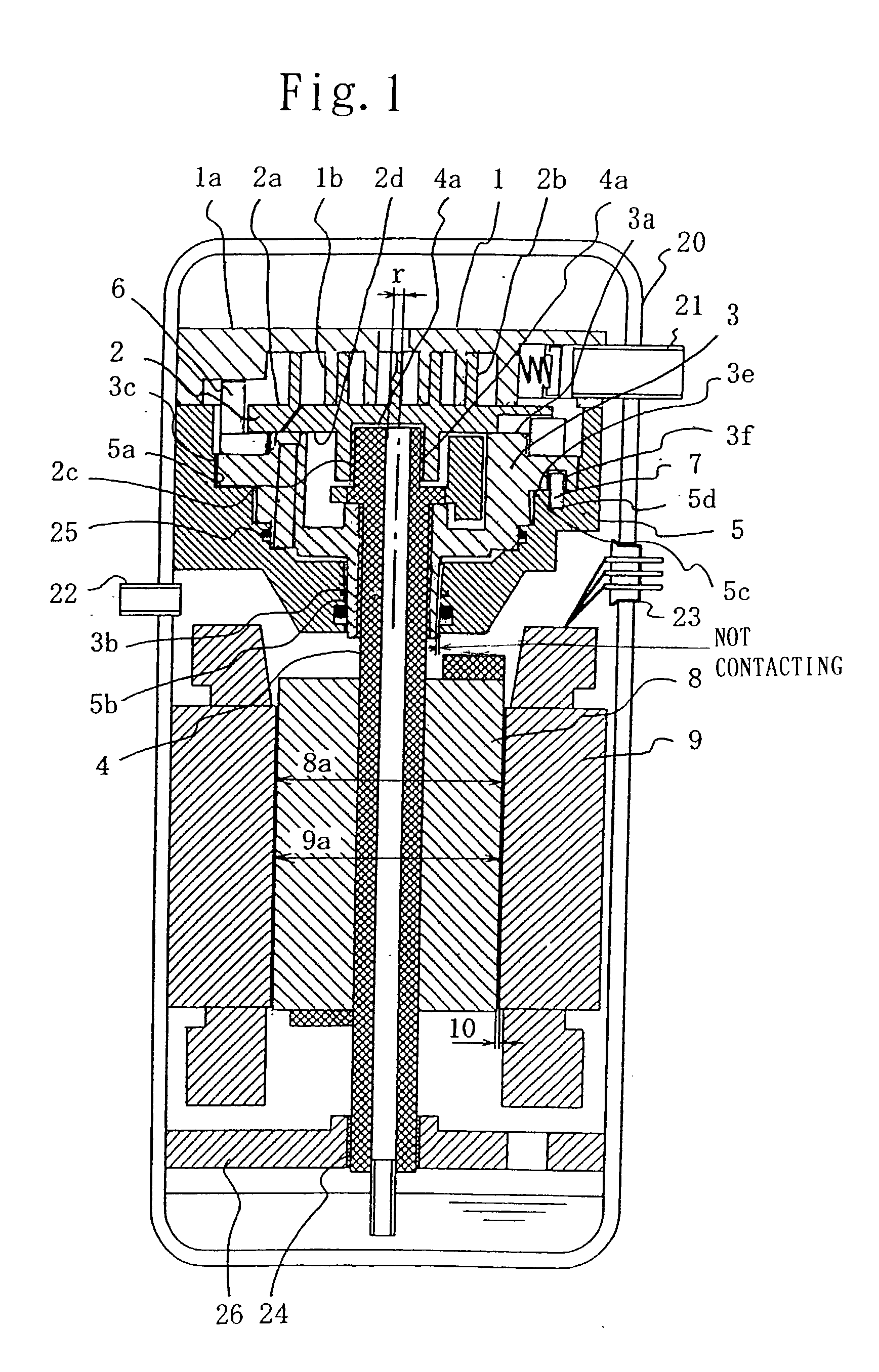
[0061] Preferred embodiments of the present invention will now be explained with reference to FIGS. 1 through 4, wherein the same numerical references as those of the conventional scroll compressor are given to the same parts or units, and descriptions of them are omitted. FIG. 1 shows a longitudinal section view of a compression mechanism part of a scroll type refrigerant compressor according to Embodiment 1. In FIG. 1, the following is provided: a fixed scroll 1 which is fixed to a hermetic container 20, a seat 1a of the fixed scroll 1, a spiral blade 1b of the fixed scroll 1, an orbiting scroll 2, a seat 2a of the orbiting scroll 2, and a spiral blade 2b of the orbiting scroll 2. An orbiting bearing 2c is provided at a central part of the surface of the orbiting scroll 2 opposite to the surface where the spiral blade 2b exists. A thrust surface 2d is formed on the end of the surface where the orbiting bearing 2c is provided. The orbiting scroll 2 is connected with an eccent...


PUM


Abstract

According to a scroll compressor of the present invention, at least one of a diameter space between an upper fitting surface of the guide frame and an upper fitting surface of the compliant frame at an upper fitting part where the upper fitting surface of the guide frame contacts with the upper fitting surface of the compliant frame, and a diameter space between a lower fitting surface of the guide frame and a lower fitting surface of the compliant frame at a lower fitting part where the lower fitting surface of the guide frame contacts with the lower fitting surface of the compliant frame is set to be equal to or shorter than a diameter space between the rotor and the stator.

Description

[0001] 1. Field of the Invention[0002] The present invention relates to a scroll compressor used for a refrigerating machine, an air conditioner and the like.[0003] 2. Description of the Related Art[0004] FIG. 5 shows a longitudinal sectional view of a compression mechanism part of a conventional scroll type refrigerant compressor disclosed in Japanese Unexamined Patent Publication No. 2000-337276. In FIG. 5, a fixed scroll 1, a seat 1a of the fixed scroll 1, a spiral blade 1b of the fixed scroll 1, an orbiting scroll 2, a seat 2a of the orbiting scroll 2, and a spiral blade 2b of the orbiting scroll 2 are provided. An orbiting bearing 2c is provided at a central part of the surface of the orbiting scroll opposite to the surface where the spiral blade 2b of the orbiting scroll 2 exists. A thrust surface 2d is formed on the end of the surface where the orbiting bearing 2c is provided. The orbiting scroll 2 is connected with an eccentric part 4a of a main shaft 4 through the orbiting ...

Claims


Application Information

Patent Timeline
IPC IPC(8): F04B39/12F04C18/02F04C23/00F04C29/00
CPCF04C18/0215F04C23/008F04C2270/72F04C2240/10F04C29/0021
Inventor SANO, FUMIAKISEKIYA, SHINIKEDA, KIYOHARUFUSHIKI, TAKESHIOGAWA, YOSHIHIDENISHIKI, TERUHIKOSEBATA, TAKASHITANI, MASAO
Owner MITSUBISHI ELECTRIC CORP
Why Eureka
Eureka Blog
Learn More