System and method for diagnosing aircraft components for maintenance purposes

a technology for aircraft components and maintenance, applied in process and machine control, instruments, navigation instruments, etc., can solve the problems of difficult if not economically impossible to simulate actual flight conditions on the ground for maintenance purposes, the entire aircraft begins to vibrate, and the fault is difficult to detect on the ground, etc., to achieve cost reduction, maintenance costs, and time reduction

Inactive Publication Date: 2003-05-01
AIRBUS OPERATIONS GMBH
View PDF15 Cites 107 Cited by
  • Summary
  • Abstract
  • Description
  • Claims
  • Application Information

AI Technical Summary

Benefits of technology

[0006] to facilitate the maintenance of aircraft, particularly commercial aircraft, by a rapid and certain recognition and locating of faults in aircraft components or component assemblies so that replacement of components or component assemblies which are still perfectly operational is avoided;
[0007] to provide maintenance information and / or instructions to the maintenance personnel which enables the performance of the maintenance and repair work with a reduced effort and expense compared to the prior art while reducing the maintenance and repair time;
[0009] to transmit sensed and stored component status information from the aircraft to a signal processing unit in a wireless manner so that maintenance personnel can perform a checking sequence without actually inspecting any particular component inside the aircraft.
[0016] It is a particular advantage of the invention that maintenance costs which constitute a substantial component of the current operating costs of a commercial aircraft, have been substantially reduced. These cost reductions are particularly due to the fact that the present system is capable of checking the aircraft components and / or component assemblies with certainty as to the presence and location of any faults in a substantially reduced time compared to prior art maintenance operations. Moreover, by providing the maintenance personnel with diagnostic information that is based on actual measured values even values measured during flight time, maintenance operations are facilitated by directly pointing out what needs to be done and exactly where. Further, by separating the information gathering from the information processing and evaluation, the maintenance operations are made simpler since maintenance personnel no longer needs to enter for example into the landing gear bay while still a precise locating of a fault or nonstandard condition is precisely located for example in a particular flap actuator or in the hydraulic system or in the fuel supply system of the aircraft.
[0017] The main advantage of the present method is seen in that faulty components and / or substandard situations are precisely pinpointed or located in the entire aircraft. The replacement of perfectly good components is avoided and the overall time for all maintenance and repair operations is substantially reduced compared to the prior art.

Problems solved by technology

Due to the multitude and complexity of the aircraft components to be checked it is frequently time consuming and expensive to dismount the respective component then perform a fault check and testing of the functional capability of the particular component and then remount or reassemble the component or replace it by a new component or component assembly.
Another problem in connection with aircraft maintenance work is caused by possible faults that occur during flight but are not recognized during a check of the aircraft on the ground.
Thus, the wear and tear of the actuators of the wing flap assemblies may, for example, be overlooked although such wear and tear in these flap actuators may be the cause that the entire aircraft begins to vibrate in response to control oscillations of the flap actuators.
Such faults are hard to detect on the ground because these faults are normally not easily reproducible on the ground.
It is difficult if not economically impossible to simulate actual flight conditions on the ground for maintenance purposes.
Thus, a faulty flap actuator cannot conventionally be located with certainty.
Such replacements involve substantial costs.
Maintenance costs are a substantial proportion of the current costs of operating any commercial aircraft.

Method used


Image

  • System and method for diagnosing aircraft components for maintenance purposes
  • System and method for diagnosing aircraft components for maintenance purposes
  • System and method for diagnosing aircraft components for maintenance purposes

Examples


Embodiment Construction

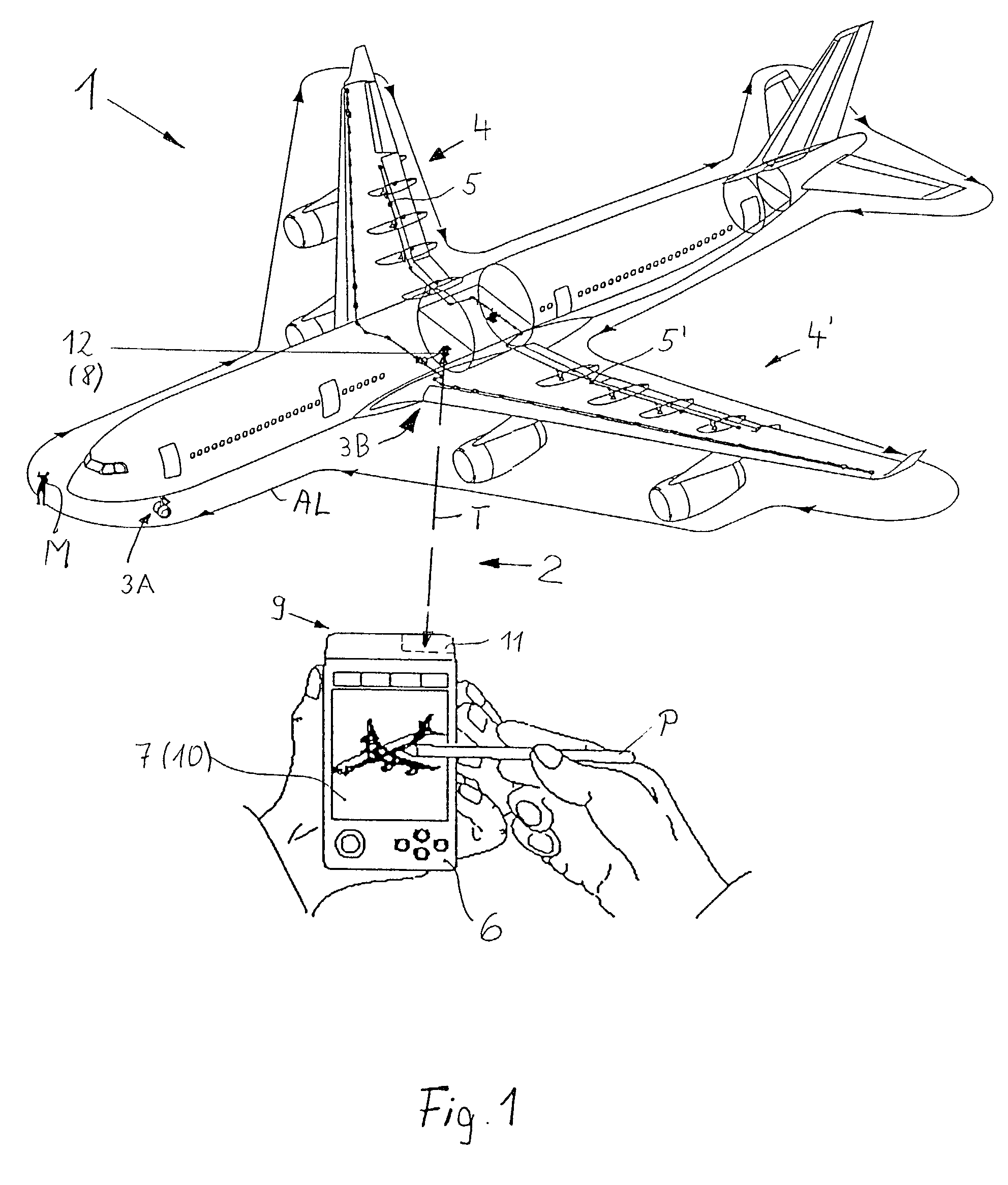
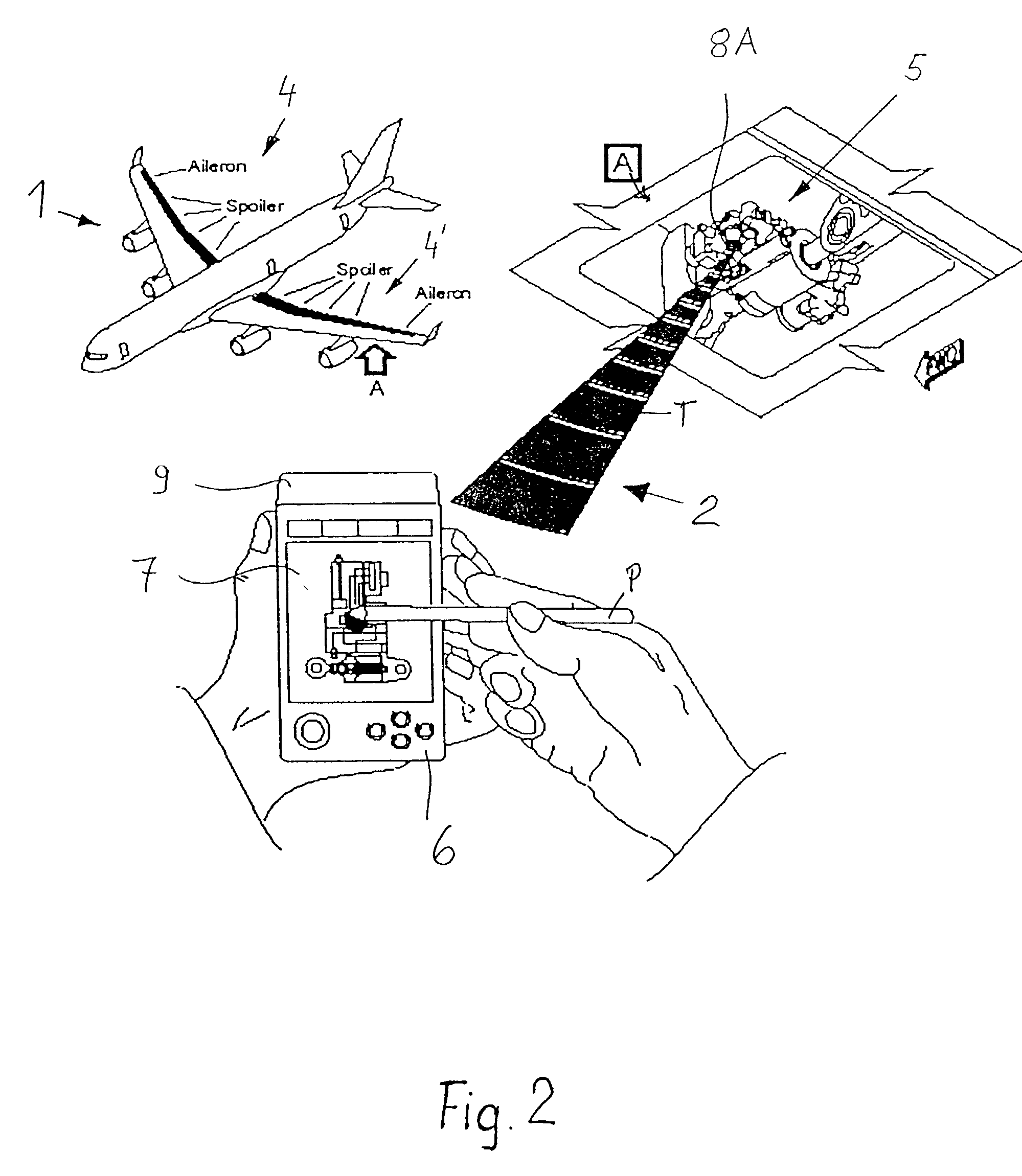
[0025] FIG. 1 shows schematically an outline of an aircraft 1 on the ground. The outline also shows examples of particular aircraft components or component assemblies to be monitored and diagnosed according to the invention. Prior to each flight it is required that a so-called "walk around check" is made by a mechanic who walks around the aircraft as indicated by the arrowed line AL. The purpose of such a check is to inspect the functional capability of important aircraft components and / or component assemblies. For example, the following components receive special attention, namely the front wheel assembly 3A, the landing wheels and gear 3B, including a check of the air pressure in the tires and a control of the brakes. Further, and among other checks, the flap assemblies 4 and 4' such as the spoiler and landing flaps and their hydraulic actuators 5, 5' of these flaps receive special attention. A problem with checking the flap assemblies 4 and 4' and the flap actuators 5 and 5' form...


PUM


Abstract

Aircraft maintenance and repair work is facilitated, especially for a commercial aircraft, by a diagnostic system and method, wherein an aircraft component or assembly of components is monitored by at least one sensor which produces and preferably also stores component status information. Respective status information signals are transmitted, preferably in a wireless manner, from a transmitter of the sensor to a receiver of a signal processing unit which provides status information on a display screen. The status information signals are preferably processed and evaluated with reference to rated maintenance and repair reference information to provide instructions as to what needs to be done where and when for a maintenance or repair. The sensor or sensors may operate during flight and the respective stored information is then processed and used on the ground.

Description

PRIORITY CLAIM[0001] This application is based on and claims the priority under 35 U.S.C. .sctn.119 of German Patent Application 101 53 151.6, filed on Oct. 27, 2001, the entire disclosure of which is incorporated herein by reference.[0002] The invention relates to a method and apparatus for diagnosing the status of aircraft components or aircraft component assemblies to provide maintenance and repair information.BACKGROUND INFORMATION[0003] It is customary to perform aircraft maintenance operations, particularly on commercial passenger aircraft, at predetermined, regular time intervals, whereby a multitude of maintenance checks must be performed. Such maintenance operations must be performed to assure the reliability and safety that is required for flight operations. Therefore, the components or component assemblies of individual aircraft types are regularly checked and / or replaced following a certain operating time duration. Due to the multitude and complexity of the aircraft comp...

Claims


Application Information

Patent Timeline
Patent Type & Authority Applications(United States)
IPC IPC(8): B64D47/00B64F5/00B64F5/60G07C3/00G07C5/00G07C5/08
CPCB64D47/00B64F5/0045G07C5/085G07C5/006G07C5/008G07C3/00B64F5/60B60C23/0479
Inventor HALM, JUERGENHECHTENBERG, KURT-VOLKERKOLANDER, WERNER
Owner AIRBUS OPERATIONS GMBH
Why Eureka
Try Eureka