
Method For The Treatment Of Air Of At Least One Room By Air Ionization

a technology of air ionization and air treatment, which is applied in the direction of lighting and heating apparatus, heating types, applications, etc., can solve the problems of over-exceeding the limit value, increasing undetected, and increasing the ozone formation with increasing voltage, so as to eliminate microorganisms, and reduce the oxidation potential of the air

Inactive Publication Date: 2003-05-08
LK LUFTQUALITAT
View PDF1 Cites 29 Cited by
  • Summary
  • Abstract
  • Description
  • Claims
  • Application Information

AI Technical Summary

Benefits of technology

[0021] The solution according to the invention is characterized furthermore by ensuring a process safety and an increase of efficiency wherein also the safe application of air-technological devices with a directed use of air circulation is provided. In this connection, for high external temperatures in summer and low temperatures in winter, considerable energy savings for cooling or heating are realized. Further advantageous effects can be derived from reconstruction of already existing and the design of new air-technological devices. These are, inter alia, lowering of the proportion of external air, in particular, for a high degree of humidity in the external air or the increase of service life of the air filters.
[0022] The ionization of the supply air and optionally additionally of the circulating air results advantageously particularly in the decomposition of gaseous volatile hydrocarbons, in the lowering of the oxidation potential of the air, and the elimination of microorganisms.
[0023] A method according to a further embodiment of the invention provides a natural feeling of comfort of the air in a room, wherein, in particular, gaseous volatile hydrocarbons are removed, the oxidation potential of the air is lowered, and microorganisms are eliminated.
[0024] According to a further embodiment of the invention, a minimum intensity of oxygen ions approximately equal to 5 % of the installed ionization capacity of the air treatment device is ensured. This corresponds to the natural conditions.
[0025] The ionization power of the at least one ionization apparatus is controlled such according to a further embodiment of the invention that it increases with increasing proportions of volatile hydrocarbons and / or increase of the air velocity and / or increase of the relative air humidity and / or increased proportion of oxidizable air components. This ensures that an air supply, that is substantially not loaded, is introduced into the room or the recreation zone as a result of the predetermined air exchange and the optimized ionization intensity when the air quality in the room deteriorates.
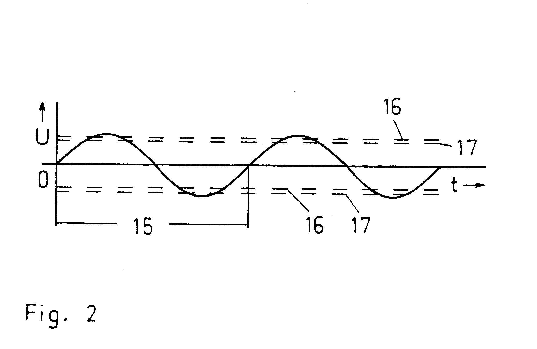
[0026] A beneficial control of the ionization apparatus is advantageously possible according to further embodiments of the invention by means of a temporally supplied periodic alternating voltage. In this connection, the ionization apparatus is loaded with alternating pulses or alternating pulses combined to packages of a periodic alternating voltage that is available. The optimized discharge voltage is constant in this connection.

Problems solved by technology

An important disadvantage is that starting at a certain voltage ozone is formed, and the ozone formation increases with increasing voltage.
When outer disturbance sources are present, i.e., an increased ozone loading in the ambient air, for example, in smog situations resulting from sun radiation, different situations in nature, for example, inverted weather situations, thunderstorms, outer energy fields, or in the case of inner disturbance sources, for example, in the form of electrical devices installed in the vicinity of air supply lines for transformation of voltage or frequencies, electromagnetic radiation, or other radiation, the loading with ozone in the supply air can increase undesirably and can lead to surpassing the limit value.

Method used


Image

  • Method For The Treatment Of Air Of At Least One Room By Air Ionization
  • Method For The Treatment Of Air Of At Least One Room By Air Ionization
  • Method For The Treatment Of Air Of At Least One Room By Air Ionization

Examples


Embodiment Construction

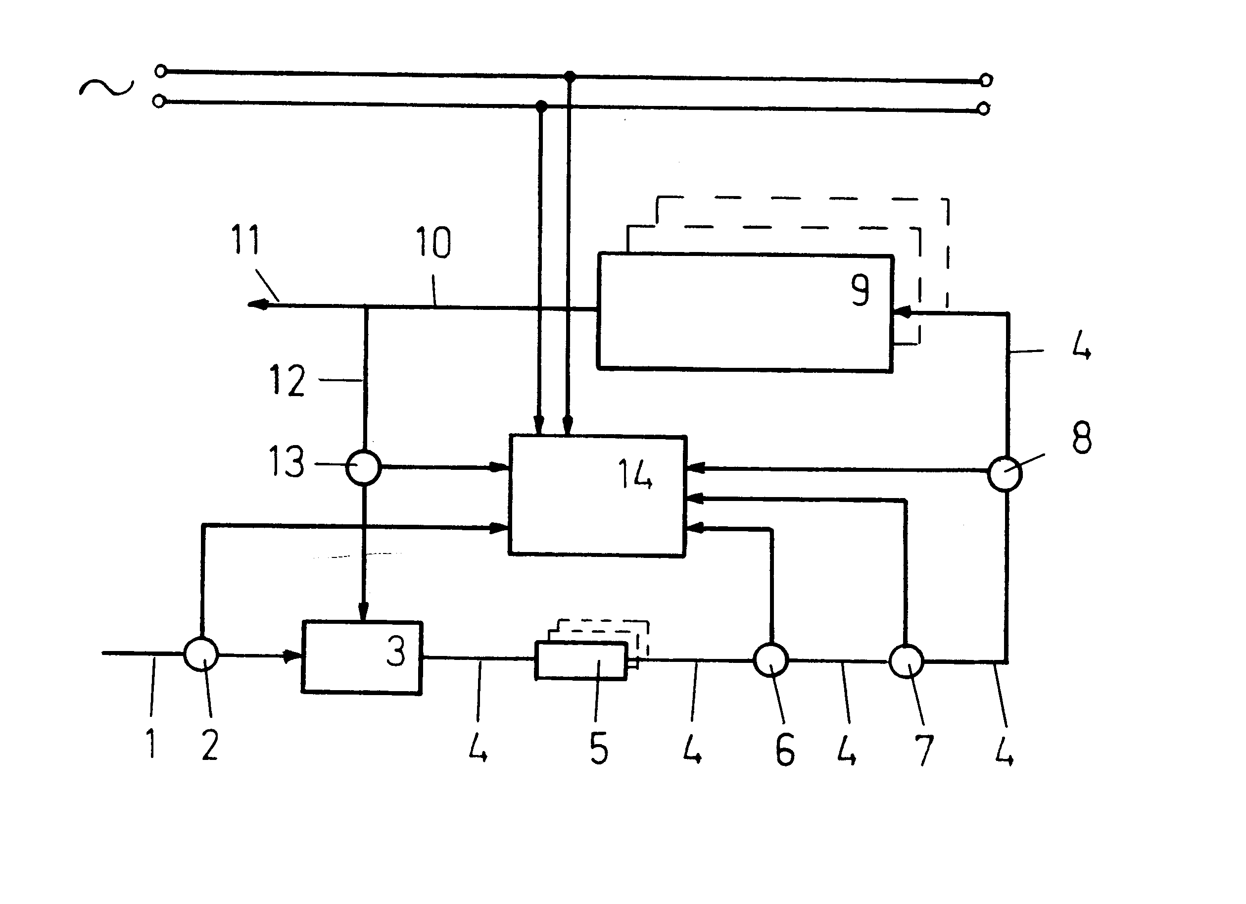
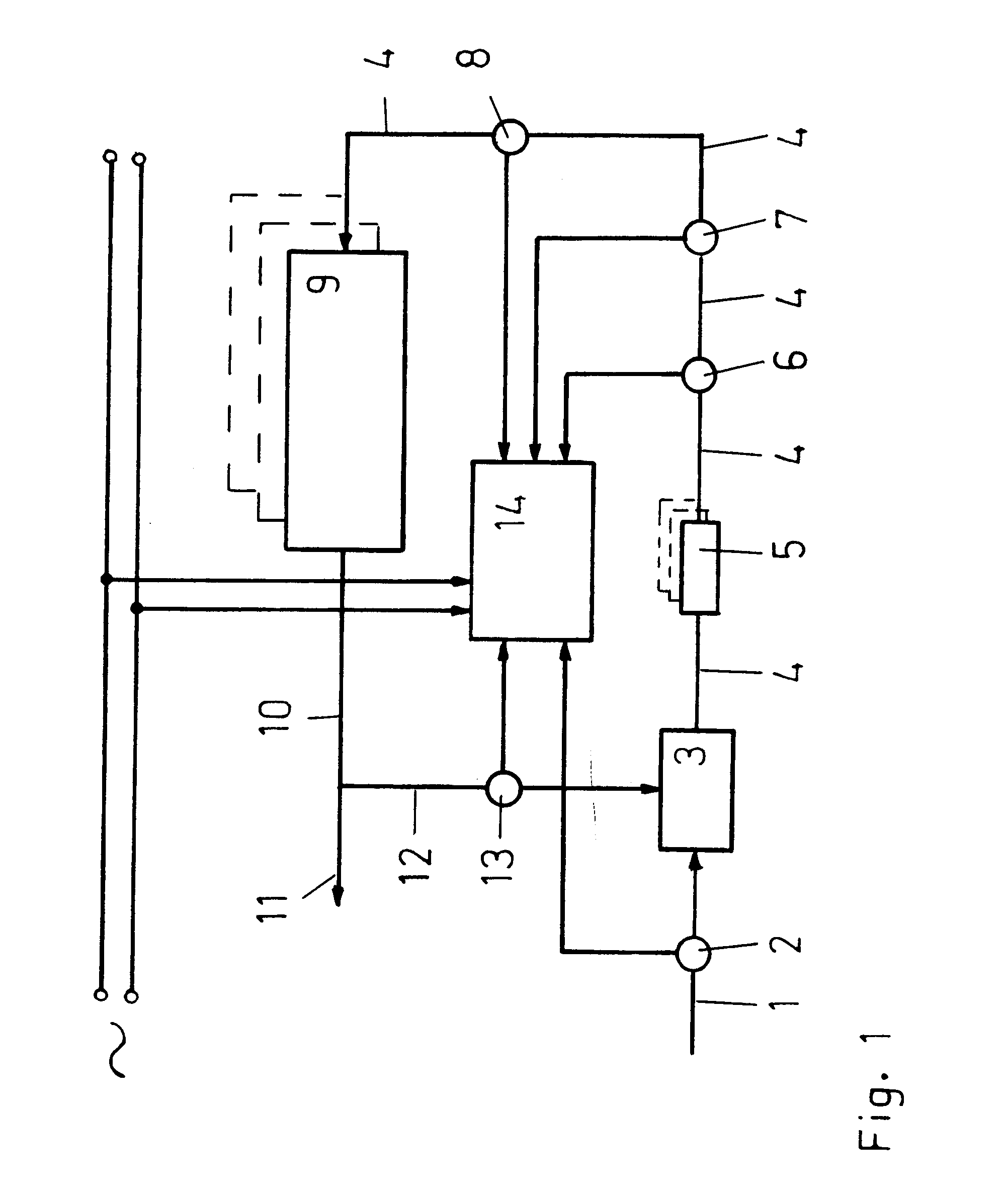
[0033] A method and a device for air treatment of at least one room 9 by ionization and thus with ions will be explained in more detail in the following with one embodiment of the invention.

[0034] Fig. 1 shows a basic schematic illustration of the device for air treatment of at least one room by air ionization. The object of the invention is to provide the room 9 with comfortable room air according to the specific requirements. Accordingly, a supply line 4 ends in this room 9.

[0035] The supply line 4 is connected to an air treatment device 3 to which is connected an external air intake 1 and the circulation line 12 coming from the room 9. The device comprises also an electronic control device 14 which is supplied with electrical power via electrical supply lines from an electrical power mains. This energy source is switched on when the air treatment device 3 is in operation wherein the supply ventilator conveys a supply flow of air.

[0036] The electronic control device 14 controls by...


PUM


Abstract

Abstract of Disclosure In a treatment method of room air by air ionization, sensors such as air-quality sensors, an airflow sensor, an air humidity sensor, an ozone sensor, are provided. Parameters such as oxidizable air components, relative humidity, flow velocity, flow volume, ozone level, and intensity of oxygen ions are measured. The level of ionization power of the ionization apparatus is determined by an electronic control device based on the measured parameters. The ionization power is lowered, when a predetermined ozone value is detected, and, when the ozone level continues to increase after lowering the ionization power indicating an external ozone source, ozone decomposition is initiated by changing a time period of the applied periodic alternating voltage, supplied in the form of alternating pulses or packages of alternating pulses of a preset number or a combination of alternating pulses and packages of alternating pulses of a preset number.

Description

Cross Reference to Related Applications[0001] This application is a continuation-in-part of pending U.S. application Ser. No. 09 / 788,287, filed February 16, 2001.Background of Invention[0002] 1. Field of the Invention.[0003] The invention relates to methods and devices for the treatment of air of at least one room by air ionization wherein this ionization is realized by electrical discharge in ionization tubes or in corona discharge tubes.[0004] 2. Description of the Related Art.[0005] It is known that the room air and thus the breathing air can be treated with ionization apparatus. In this context, bacteria and other germs are killed and large molecules are split up into smaller molecule fragments. Complex and large molecules are, inter alia, odor-causing substances so that odor can be suppressed by means of air ionization. Moreover, it is even possible to eliminate room air loading situations which are detrimental to the health of persons in the room as well as to effectively redu...

Claims


Application Information

Patent Timeline
IPC IPC(8): A61L9/22F24F3/16
CPCA61L9/22Y02B30/78F24F2011/0021F24F3/166
Inventor FLEISCHER , WERNER
Owner LK LUFTQUALITAT
Learn More