
Method for making a porous Polymeric material

a technology of porous polymer and polymer, which is applied in the direction of prosthesis, rigid container, pipe laying and repair, etc., can solve the problems of high failure rate when infection occurs, increased failure rate with decreasing caliber of blood vessel substitute, and aneurysm formation

Inactive Publication Date: 2003-05-08
KENSEY NASH CORP
View PDF10 Cites 83 Cited by
  • Summary
  • Abstract
  • Description
  • Claims
  • Application Information

AI Technical Summary

Problems solved by technology

Despite intensive efforts to improve the nature of blood vessel substitutes many problems remain, such as increasing failure rate with decreasing caliber of the blood vessel substitute, a high failure rate when infection occurs, and aneurysm formation.
This results in supply problems being some intermediate and most small diameter arteries are replaced or bypassed using an autologous saphenous vein, the long vein extending down the inside of the leg, with a secondary source being the radial veins of the arms.
In a given patient, suitable veins may be absent, diseased or too small to be used, and removal of the vein is an additional surgical procedure that carries attendant risk.
Due to the constant punishment these grafts undergo, there is a high occurrence of thrombosis, bleeding, infections, and pseudoaneurysm.
Problems associated with this type of implantation include thrombosis, infection and new aneurysm formation at the location of the stent.
Initially, autografts were used to restore continuity; however, limited supply and inadequate sizes forced the use of allografts from both donor and umbilical cord harvest such as that described in U.S. Pat. No. 3,974,526.
Even though these products were widely used they did have many drawbacks including infection, clot formation, occlusions and the inability to be used in grafts smaller than 6 mm inside diameter due to clotting.
Unfortunately, despite these positive qualities, it became clear in the early 1980s that conventional ether-based polyurethane elastomers presented long-term biostabilty issues as well as some concern over potential carcinogenic degradation products.
Further, in contrast to excellent performance in animal trials, clinically disappointing results with PU-based grafts diminished the attractiveness of the material for this application.
Specifically, the new generation of polyurethanes solved the biostabality problems but still provide clinically disappointing results.
Poor performance is largely due to limitations of current manufacturing techniques that create a random or non-optimal fibrous structure for cell attachment using crude precipitation and / or filament manufacturing techniques.
In each instance, there are severe shape-making limitations, e.g., the known non-fibrous methods appear to be limited to working with a relatively low viscosity liquid that can be coated onto a surface, or into which a shape-forming mandrel can be dipped.
Thus, the prior art does not seem to appreciate the desirability of a prosthesis such as a vascular graft containing channels or porosity extending continuously from the exterior surface to the luminal surface of the graft.
This plug continues to grow, resulting in occlusion of the graft.
If the graft is not immediately occluded the plug functions as a cell matrix increasing the potential for rapid smooth muscle cell hyperplasia.
Other reasons for artificial graft failure are neointima sloughing due to poor attachment and aneurysm formation resulting from compliance mismatch of the new graft material to the existing vascular system.
This mismatch may increase stress at the anastomotic site, as well as create flow disturbances and turbulence.
Additionally, poor attachment geometry can lead to the problematic results above, due to flow disturbances and turbulence.
For example, the harvesting of autograft veins typically causes a surgeon to use a graft of non-optimal diameter or length.
Such flow disturbances may lead to para-anastomotic intimal hyperplasia, anastomotic aneurysms, and the acceleration of downstream atherosclerotic change.
Finally, artificial graft failures have been linked to leaking of blood through the device.
One problem with this approach is that the same open fibrous weave that permits blood leaking also allows the viscous bioabsorbable substances and clotted blood to accumulate on the luminal surface and easily detach resulting in complications (e.g., emboli) downstream from the device.

Method used


Image

  • Method for making a porous Polymeric material
  • Method for making a porous Polymeric material
  • Method for making a porous Polymeric material

Examples


example

[0084] A siloxane-based macrodiol, aromatic polyurethane, supplied by Aortech Biomaterials, was selected for this example.

[0085] 1) The manufacturer identified dimethyl acetimide, n-methyl pyrrolidinone, and tetrahydrofuran as solvents for the polymer.

[0086] 2) A 0.25-gram sample of polymer was placed into the bottom of 20 small bottles. Five milliliters of 20 common laboratory solvents, including the three listed by the manufacturer, was added to the bottles. The bottles were left for 48 hours at room temperature after which they were used to identify those solvents that dissolved or resulted in swelling of the polymer. Twelve polymers were identified and are listed below along with freezing point ("F.P.", also known as melt point), boiling point ("B.P."), vapor pressure ("V.P."), and solvent group (S.G.). (Other properties that can aid in the selection of solvent and gelling solvent include, but are not limited to, density, molecular weight, refractive index, dielectric constant, ...


PUM

PropertyMeasurementUnit
Volumeaaaaaaaaaa
Poreaaaaaaaaaa
Biodegradabilityaaaaaaaaaa

Abstract

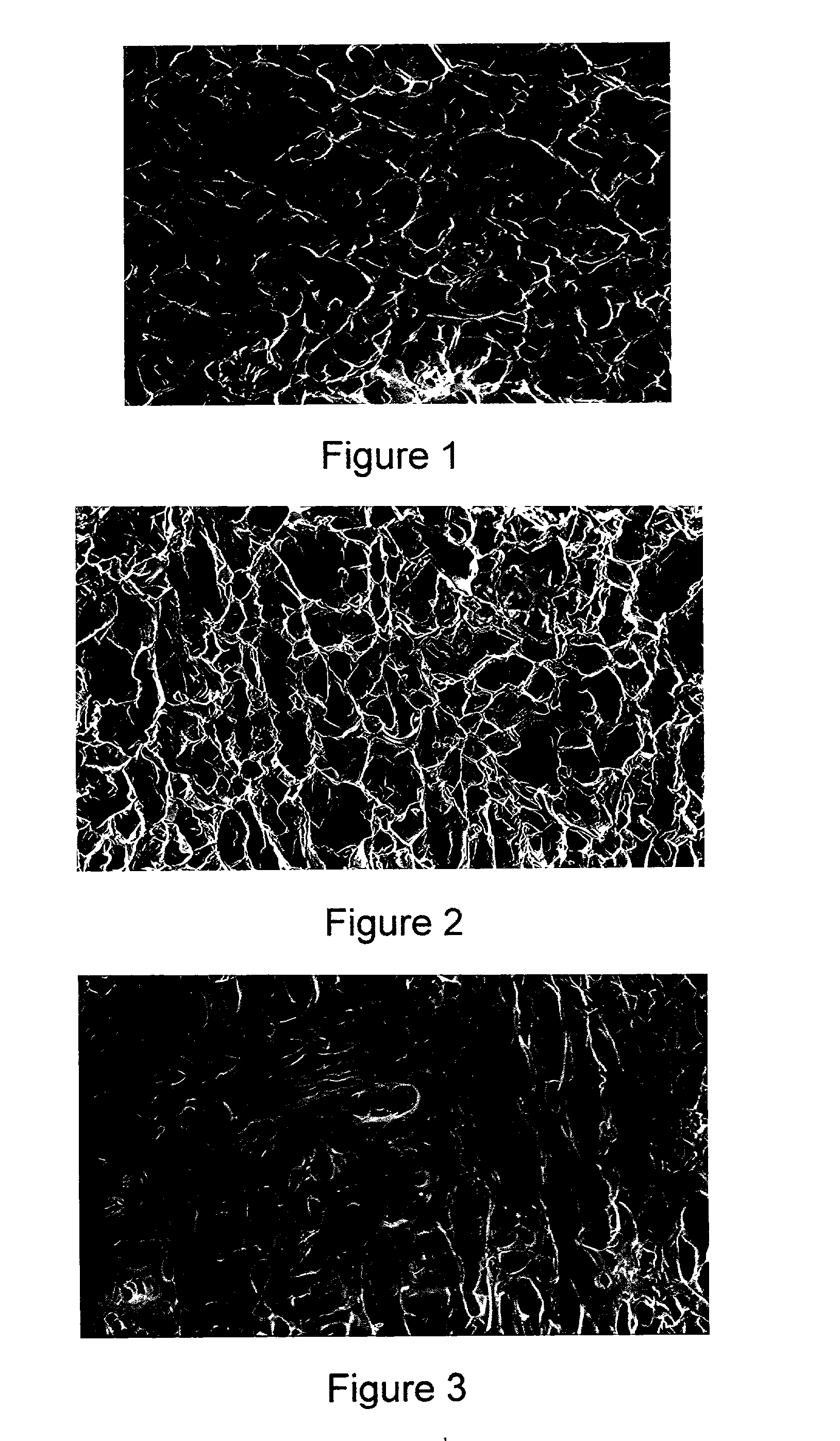
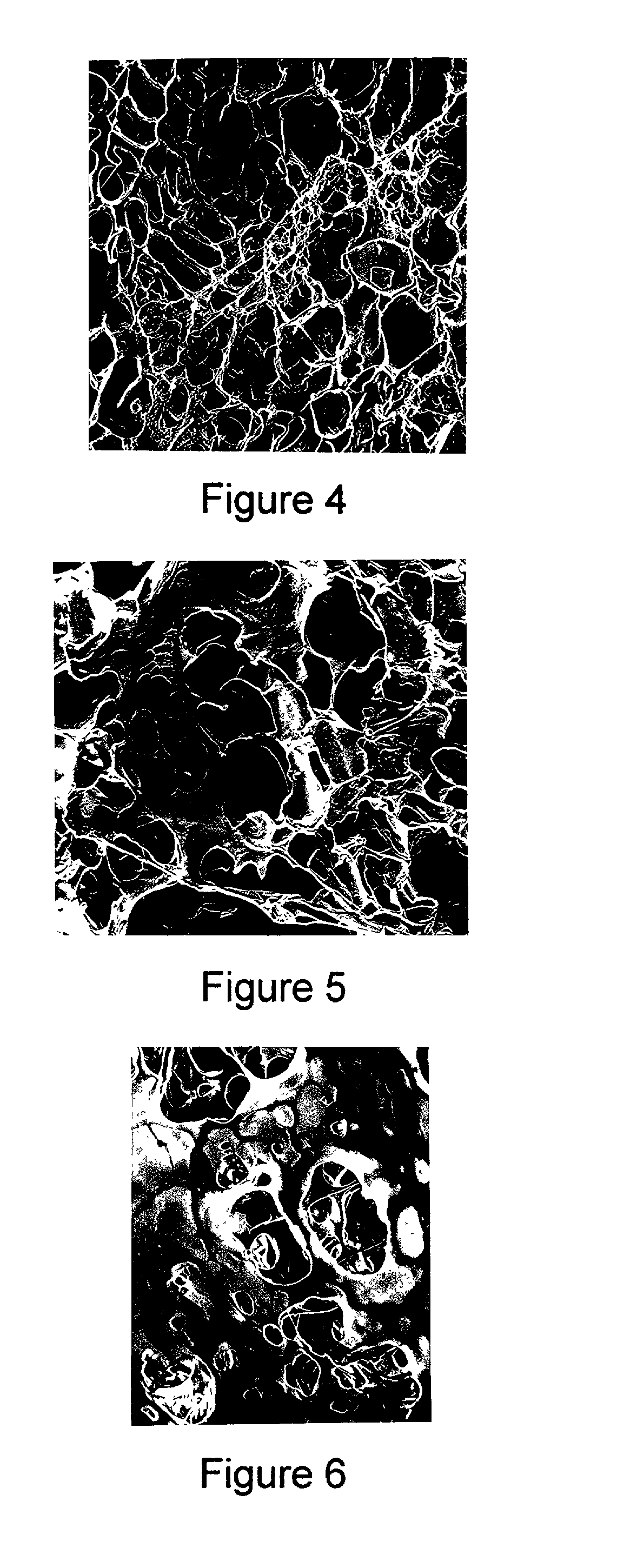
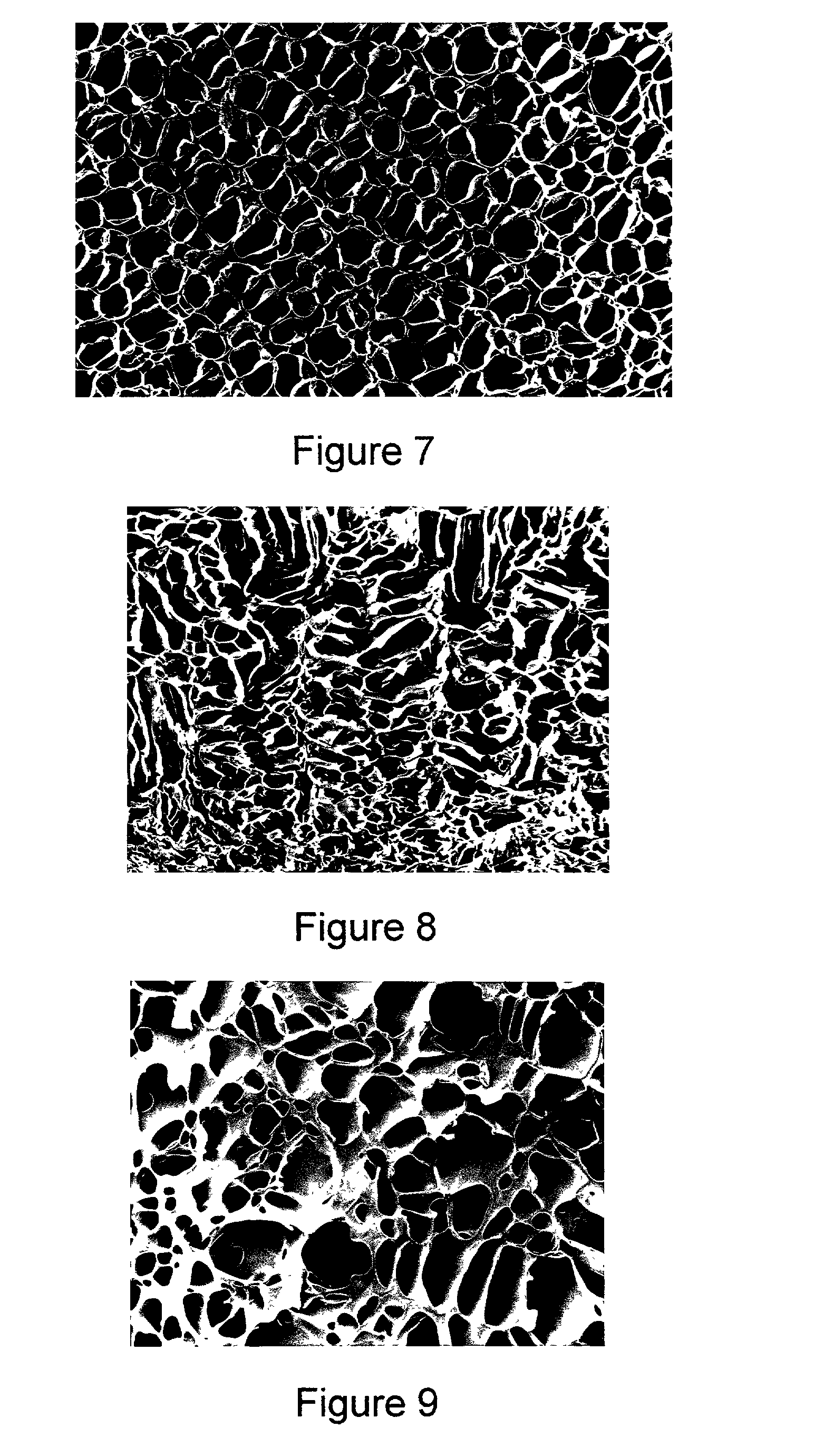
Porous polymers having a plurality of openings or chambers that are highly convoluted, with each chamber being defined by multiple, thin, flat partitions are produced by a new gel enhanced phase separation technique. In a preferred embodiment, a second solvent is added to a polymer solution, the second solvent causing the solution to gel. The gel can then be shaped as needed. Subsequent solvent extraction leaves the porous polymeric body of defined shape. The porous polymers have utility as medical prostheses, the porosity permitting ingrowth of neighboring tissue. The present technique also enhances shape-making capability, for example, of bifurcated vascular grafts, which feature a common entrance region but two or more exit regions.

Description

[0001] 1. Field of the Invention[0002] The present invention relates to an improved porous polymer useful for various applications in industry, including the medical industry, for example, as a biological prosthesis and particularly useful in vascular surgery. The porous polymer can be made by use of a new gel enhanced phase separation technique, which, among other advantages, permits enhanced shape-making capability.[0003] 2. Statement of Related Art[0004] The present invention encompassing polymer engineering and processing came about from efforts to improve existing properties of porous polymers, including medical devices and prostheses and, in particular, medical devices (e.g., vascular grafts). Accordingly, a review of the vascular graft art is appropriate.[0005] The search for the ideal blood vessel substitute has to date focused on biological tissues and synthetics. Despite intensive efforts to improve the nature of blood vessel substitutes many problems remain, such as incre...

Claims


Application Information

Patent Timeline
IPC IPC(8): A61F2/00A61F2/04A61F2/06A61K9/14A61L27/14A61L27/56B29C65/00B29D22/00B29D23/00B32B1/08B65D1/00C08F2/00C08F283/04C08J3/00A61L27/00C08J9/00C08J9/28C08J11/00C08K3/00C08L1/00C08L101/16F16L1/00
CPCA61L27/18Y10T428/1386A61L27/52A61L27/54A61L27/56A61L2300/114A61L2300/236A61L2300/252A61L2300/406A61L2300/42A61L2300/43A61L2300/64A61L2300/802C08J9/28C08J2201/054A61L27/48Y10T428/139C08L75/04
Inventor RINGEISEN, TIMOTHY
Owner KENSEY NASH CORP
Learn More