Consolidated body fluid testing device and method

Inactive Publication Date: 2003-06-12
KLOEPFER DR HANS
View PDF15 Cites 172 Cited by
  • Summary
  • Abstract
  • Description
  • Claims
  • Application Information

AI Technical Summary

Benefits of technology

0038] In another embodiment, the removable lancet cap has been replaced with a living hinge snap cap. In this embodiment the cleaning swab is enclosed within the snap cap. The exterior side of the snap cap features a dome shaped pressure cup for sample enlargement (when necessary), activated by pressing the cup against the lanced site. This pressure against the lanced site helps to enhance the flow of blood from the lanced site, thus ensuring a sufficient supply of blood to meet the quantity needs of the test strip and meter.
0039] Another aspect of the consolidated testing device feature of the present invention is that it reduces the number of separate items that the user must handle from about six items to a single item. Current SMBG systems require at least h

Problems solved by technology

From a provider perspective, the main shortfall is that current systems are generally limited to the measurement of glucose.
From a user point of view, there are still limitations in those features that consumers and users believe to be important, such as (1) minimal invasiveness; (2) speed of analysis and (3) ease of performance and minimal complexity (inconvenience) from primary and auxiliary product mixes.
Non-invasive and minimally invasive technologies (such as the one of the instant invention) have been under active development for years, but made it to market only on a very limited scale due to technical difficulties.
However, since the two can usually not be completely spatially separated, pure signals are by definition unobtainable.
Unfortunately, the important feature of visual backup is realized only in a minority of present systems.
This limitation resides in the method by which cellular component of blood is separated from plasma.
Cells were then manually removed from the site of blood application by either washing or wiping them away, potentially giving rise to significant operator-induced errors.
The dream goal for the SMBG

Method used


Image

  • Consolidated body fluid testing device and method
  • Consolidated body fluid testing device and method
  • Consolidated body fluid testing device and method

Examples


Embodiment Construction

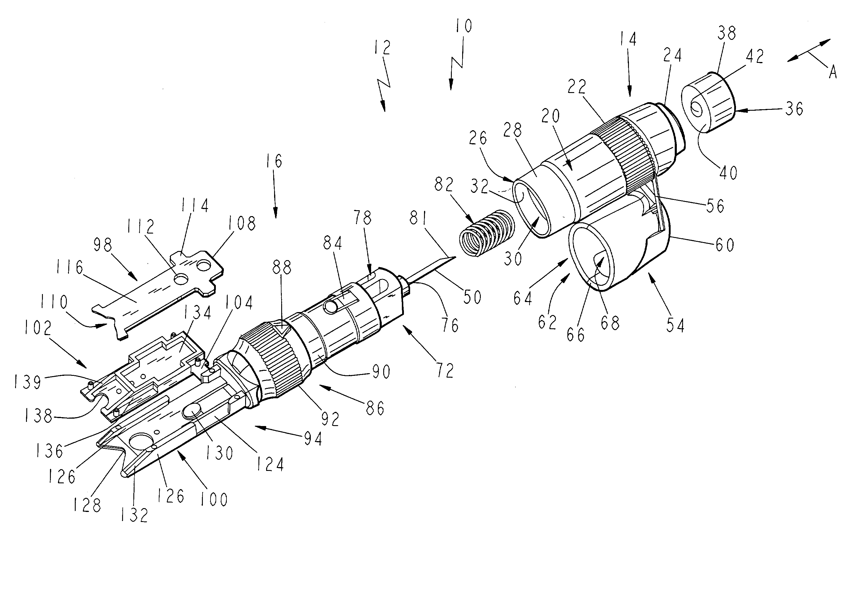
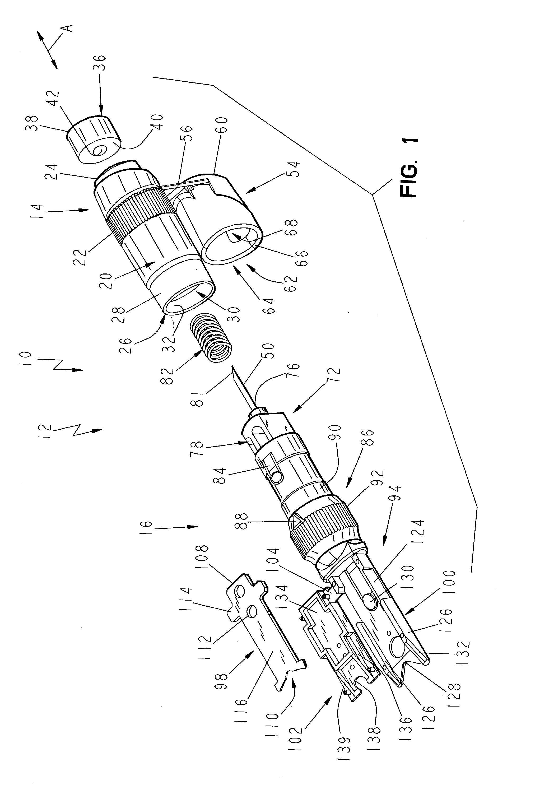
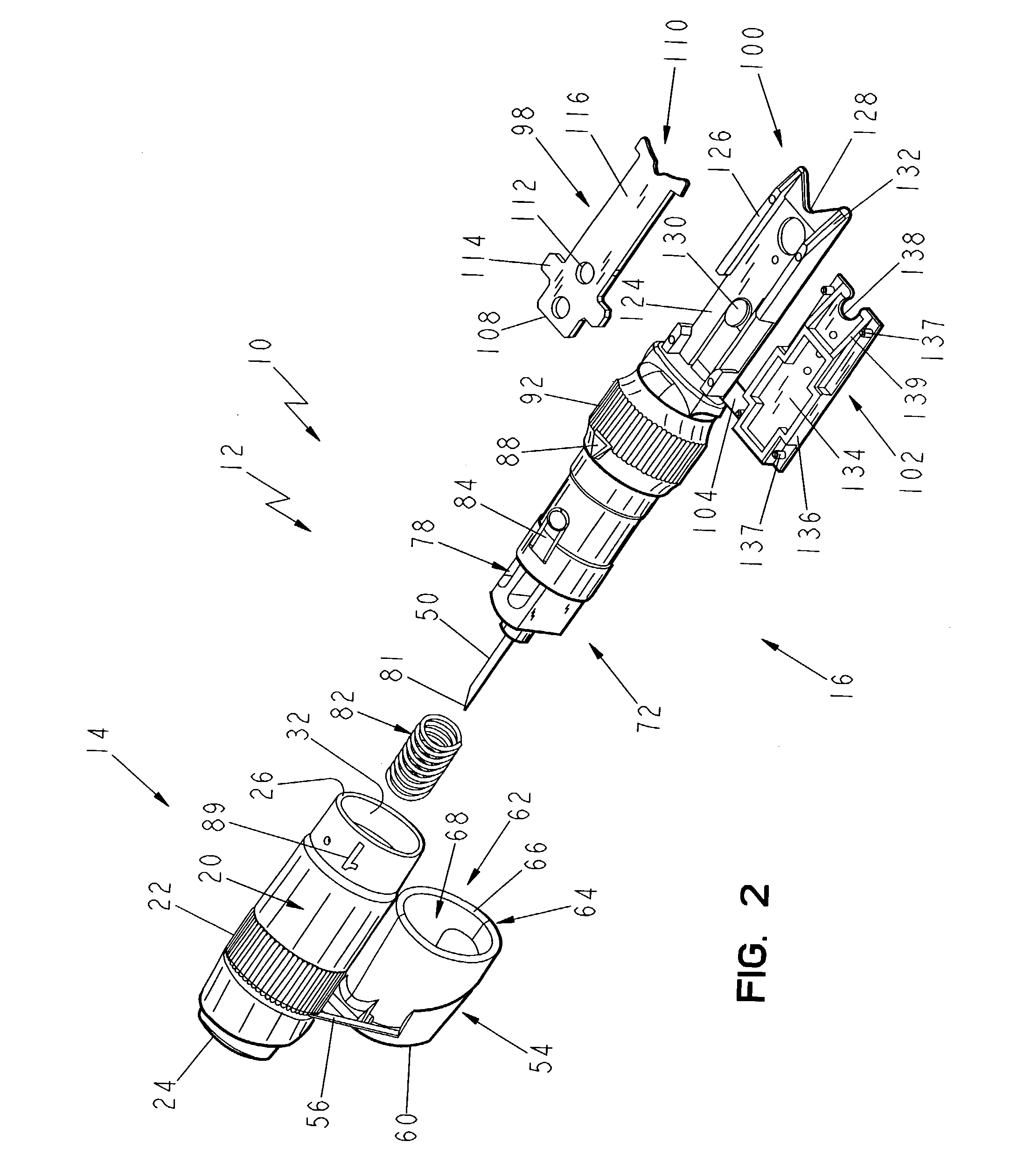
[0068] The first embodiment of the testing device 10 of the present invention is shown in FIGS. 1-4 as including a body 12 that includes a first end body portion 14 that is attachable to and joinable with a second body portion 16 to form the assembled testing device 10, as shown in FIGS. 3 and 4. The testing device 10 is generally pen-shaped, and includes a longitudinally extending axis A, which will be used as a reference point to describe the various surfaces and directional extent of the components of the testing device 10. The first end body portion 14 includes a radially outwardly facing cylindrical surface 20 having a knurled or otherwise roughened gripping surface 22 for enhancing the user's ability to grip and control the device 10. The first end body portion 14 also includes an arbitrarily designated proximal end 24 and a distal end 26. A reduced diameter portion 28 is disposed adjacent the distal end 26. The reduced diameter portion 28 is sized for interiorly receiving the...


PUM


Abstract

A body fluid testing device includes a body member and a tissue penetrator carried by the body member. A test strip holder is carried by the body member, and a test strip is carried by the test strip holder. The test strip is capable of receiving a body fluid thereon and processing the body fluid into a form suitable for yielding test results relating to the content of the body fluid.

Description

I. CLAIM OF PRIORITY[0001] The instant application claims priority to Kloepfer, Kloepfer and Roach, U.S. Provisional Patent Application No. 60 / 340,442 filed Dec. 7, 2001.II. TECHNICAL FIELD OF THE INVENTION[0002] The present invention relates to methods and devices for testing analysis fluids, and more particularly to a consolidated testing apparatus for use in performing analyses of one or more components of a fluid. Significant contemplated applications of the invention are in the biological sciences, especially diagnostic medicine. In this field, analysis fluids would primarily be bodily fluids, notably whole blood.III. BACKGROUND OF THE INVENTION[0003] A. Overview of Disease Conditions Warranting a Need for the Present Invention.[0004] Diabetes has been referred to as the "undiagnosed epidemic of the third millennium". Some experts predict the number of diabetics world-wide to triple over the next 15 years to about 320 million. Self-monitoring of blood glucose (SMBG) is consider...

Claims


Application Information

Patent Timeline
IPC IPC(8): A61B5/15
CPCA61B5/1411A61B2562/0295A61B5/15142A61B5/151A61B5/150022A61B5/150068A61B5/150183A61B5/150259A61B5/150358A61B5/150412A61B5/150503A61B5/150824A61B5/15113A61B5/15117A61B5/1519
Inventor KLOEPFER, HANS G.HAFELLNER, REINHARDROACH, CHARLES W.THOMECZEK, CHARLES
Owner KLOEPFER DR HANS
Why Eureka
Try Eureka