Analog bi-phase modulation

a bi-phase modulation and analog technology, applied in phase-modulated carrier systems, synchronous/start-stop systems, digital transmission, etc., can solve the problems of not being able to transmit analog (multi-level) signals such as voice, voice transmitted by this method producing very deleterious effects, and voice distorted grossly, etc., to limit the bandwidth needed to transmit

Inactive Publication Date: 2003-07-03
ALBATROSS TECH LLC
View PDF3 Cites 0 Cited by
  • Summary
  • Abstract
  • Description
  • Claims
  • Application Information

AI Technical Summary

Benefits of technology

0009] Yet a further object of the invention is to provide quality communications while limiting the bandwidth needed to transmit the signal.

Problems solved by technology

In this simple bi-phase method, the signal consists of only 2 designated levels, but it is not at all suitable for transmitting analog (multi-level) signals such as voice.
Because this method uses only designated signal reversal with fixed timing, voice transmitted by this method produces very deleterious effects.
First, (hard limited) voice is grossly distorted.
Secondly, because the prior art method requires that the signal be at full amplitude at all times, gaps between words are filled with noise, making this method very difficult for the listener to endure.
Whereas FM in principle is easy to understand, it is much more complex for the engineer to explain in technical terms.
However, to the engineer or statistician this simple frequency sweep involves a complex Bessel function that spreads the frequency band in a very complex manner.
FM is in wide use today, especially for broadcast, because of its noise suppression characteristics, but its noise suppression characteristic comes with a significant bandwidth penalty.
Wider bandwidth also invites wider bandwidth noise.
Voice, music, and other typical analog signals however have relatively wide dynamic range, and noise suppression demands even greater bandwidth spreading.
Furthermore, greater bandwidth spreading lowers the noise suppression "threshold", below which noise suppression breaks down entirely, and the signal becomes unusable.
In other words, bandwidth spreading suppresses noise when the signal level is strong, but reduces its performance in weak signals.
Optimum noise suppression is obtainable only when the modulating signal is at full amplitude level But the dynamic range of analog signals can be very large, making it difficult or impossible to keep the signal level at full amplitude all the time.
This is impossible for FM signals, since wide dynamic range demands that much of the time the signal is at low levels, providing low noise suppression.

Method used


Image

  • Analog bi-phase modulation
  • Analog bi-phase modulation
  • Analog bi-phase modulation

Examples


Embodiment Construction

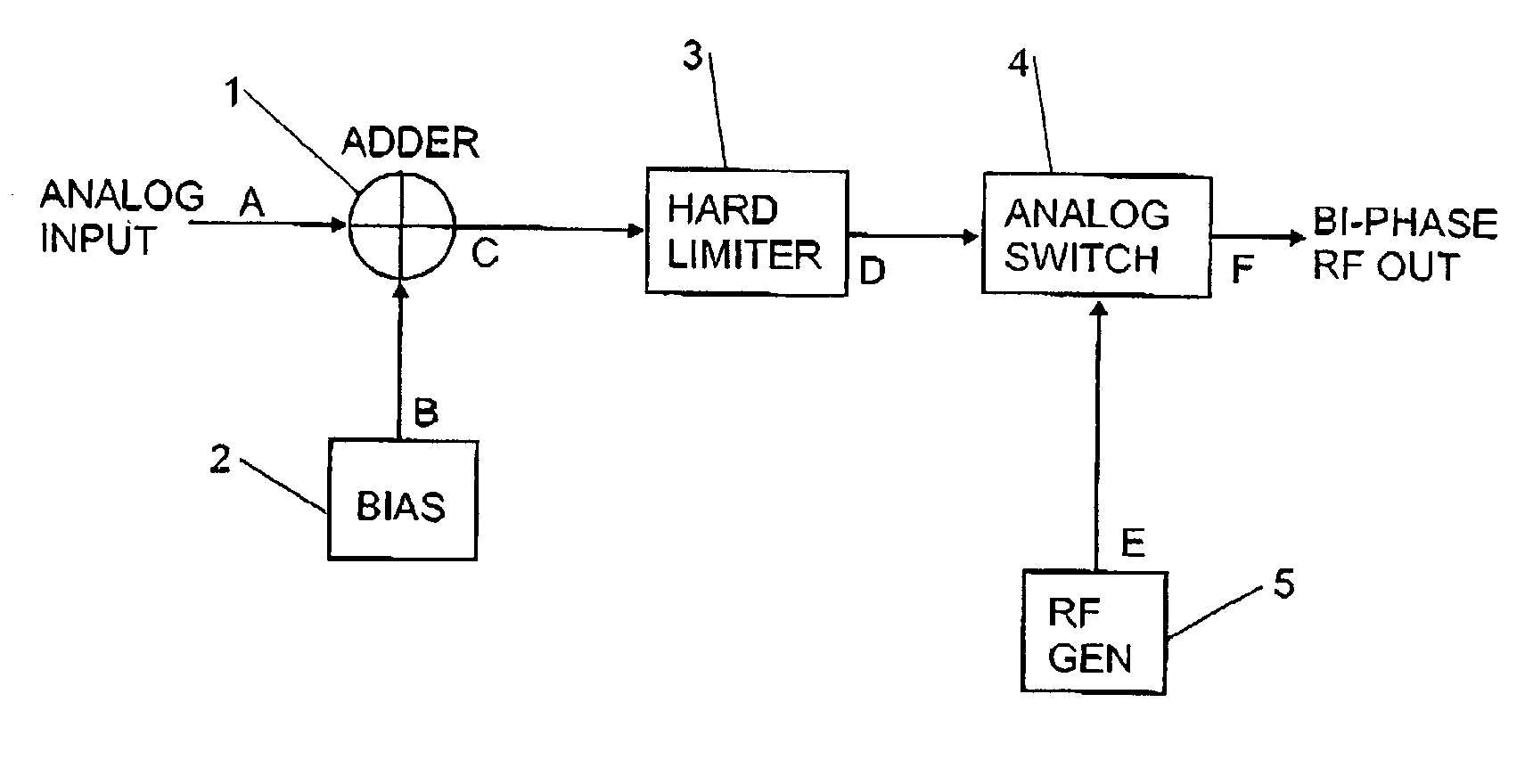
[0041] FIG. 1 shows a block diagram of an ABPM transmitter,

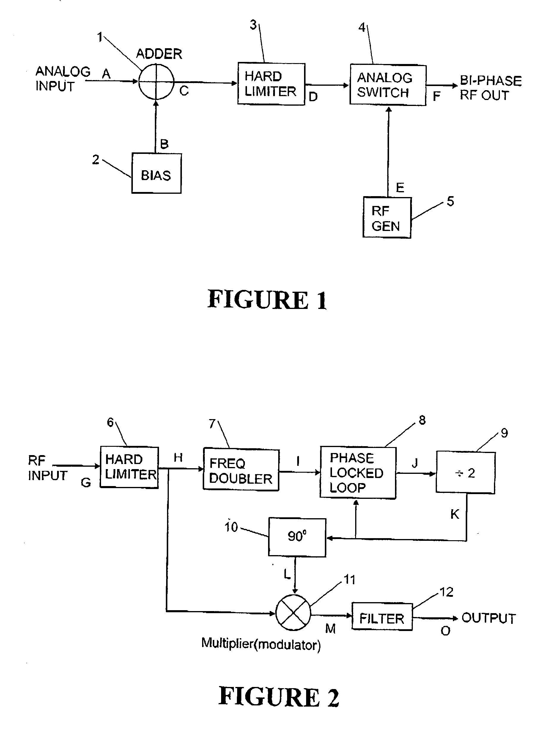
[0042] FIG. 2 shows a block diagram of a receiver for demodulating ABPM,

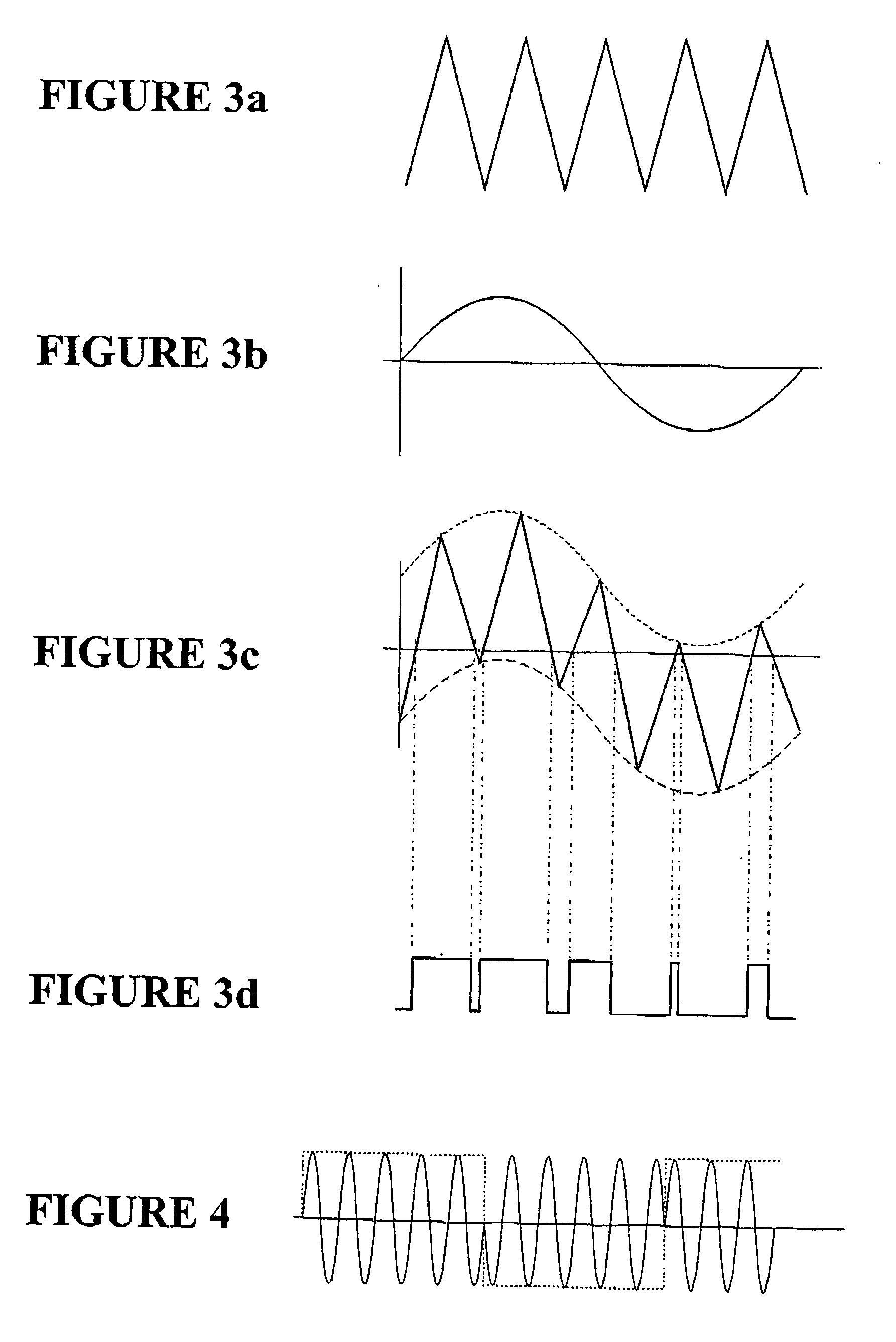
[0043] FIG. 3(a) shows a triangular bias signal,

[0044] FIG. 3(b) shows a sinusoidal input or message signal,

[0045] FIG. 3(c) shows the sum of the bias and input signals,

[0046] FIG. 3(d) shows the output of hard limiting the waveform of FIG. 3(c), and

[0047] FIG. 4 shows a carrier signal modulated by the waveform of FIG. 3(d).

[0048] FIG. 1 is a simplified block diagram of a transmitter according to the preferred form of the invention and will be explained with reference to the waveform diagrams of FIGS. 3 and 4. Analog information signal A (see FIG. 3(b) is added to a triangular or sinusoidal bias signal B (see FIG. 3(a) produced by bias generator 2, in adder 1. The combined signal C (see FIG. 3(c) is then converted to a square wave D (see FIG. 3(d) by hard limiter 3. The amplitude of the bias is set to be always larger than the information signal. This en...


PUM


Abstract

An analog modulation technique where the message information is contained in the timing of phase reversal zero crossings in the transmitted signal. In the preferred implementation a bias signal is added to an information signal and the composite signal hard limited to produce a square wave. The square wave is used to switch the phase of a carrier signal so that phase reversals occur in correspondence with the change in polarities of the square wave. A demodulation technique is also disclosed.

Description

[0001] This invention relates to a modulation system for improved communications and in particular an analog bi-phase modulation technique where the message information is contained in the timing of phase reversal zero crossings of the transmission signal.DESCRIPTION OF THE PRIOR ART[0002] Bi-Phase Modulation (BBPM) has been used in transmission of binary (2-level) data. In this simple bi-phase method, the signal consists of only 2 designated levels, but it is not at all suitable for transmitting analog (multi-level) signals such as voice. Because this method uses only designated signal reversal with fixed timing, voice transmitted by this method produces very deleterious effects. First, (hard limited) voice is grossly distorted. Secondly, because the prior art method requires that the signal be at full amplitude at all times, gaps between words are filled with noise, making this method very difficult for the listener to endure.[0003] Frequency modulation (FM) has well known attribu...

Claims


Application Information

Patent Timeline
Patent Type & Authority Applications(United States)
IPC IPC(8): H04L25/49H04L27/18
CPCH04L27/18H04L25/4902
Inventor WEBB, JOSEPH ALFRED
Owner ALBATROSS TECH LLC
Why Eureka
Try Eureka