Method and arrangement for the deep resolved optical recording or a sample

a deep resolution, optical recording technology, applied in the field of microscopy, can solve the problems of multiple detection devices, reduced depth resolution through the slit diaphragm, and increased difficulty in obtaining sample data, and achieve the effect of high optical resolution

Inactive Publication Date: 2003-07-17
CARL ZEISS MICROSCOPY GMBH
View PDF4 Cites 59 Cited by
  • Summary
  • Abstract
  • Description
  • Claims
  • Application Information

AI Technical Summary

Benefits of technology

0026] It is the primary object of the invention to provide a novel method by which the preparations can be imaged in real time and with high optical resolution.

Problems solved by technology

It is disadvantageous in this method that the depth resolution through the slit diaphragm is reduced by a factor of 1.4 compared with point-scanning laser scanning microscopes, This is due to the fact that the confocal slit diaphragm suppresses only fluorescent light components outside of the confocal section at right angles to the scan line.
Lateral resolution is also worse.
A further disadvantage in previous methods for real time microscopy consists in that multiple detection devices must be provided when a plurality of dyes are examined simultaneously.
This heightens the requirements for data transfer and increases the cost of a device of this kind.

Method used


Image

  • Method and arrangement for the deep resolved optical recording or a sample
  • Method and arrangement for the deep resolved optical recording or a sample
  • Method and arrangement for the deep resolved optical recording or a sample

Examples


Embodiment Construction

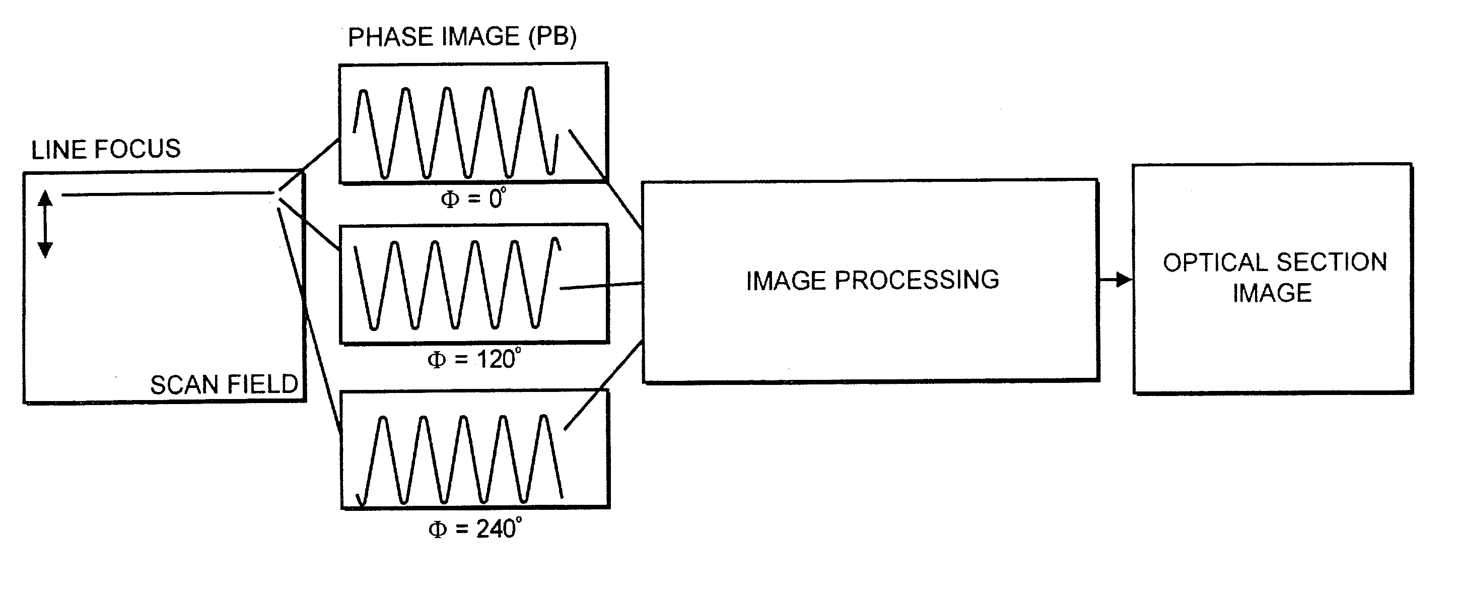
[0059] The object of the method for increasing spatial detection resolution, preferably in a method displaying images in real time, is a line-shaped excitation and detection of the excitation radiation and / or excited fluorescence reflected, scattered and / or transmitted by a specimen. For this purpose, a line focus of the excitation radiation is generated in the specimen by means of suitable optics which are described more fully in the following. FIG. 4 shows a possible measurement flow chart. A scan field with the line focus is shown on the left-hand side. The line focus can be displaced along the arrow by suitable auxiliary means (scanner mirror in one direction). The increase in axial and lateral resolution is carried out by means of a structuring of the line focus. The structuring is carried out by superposing the scan line with a periodic structure which is generated, for example, by a sine grating in the beam path. With coherent illumination, a structure can also be generated i...


PUM

PropertyMeasurementUnit
thicknessaaaaaaaaaa
edge lengthaaaaaaaaaa
angleaaaaaaaaaa

Abstract

A method for depth-resolved optical detection of a specimen comprises the steps of providing a scanning movement over the specimen or at least a part of the specimen of an illumination light distribution of at least one wavelength which is generated on or in the specimen, providing detection particularly of the light which is influenced based on interaction with the specimen, especially fluorescent light and/or reflected light and/or luminescent light and/or scattered and/or transmitted light, the illumination light having a modulation in at least one spatial direction, and carrying out the scanning movement and detection associated with the scanning with the scanning movement at least in a first and a second different phase position of the modulation and/or first and second frequency of the periodicity of the modulation and calculating at least one optical section image through the specimen or through part of the specimen. Other methods and arrangements are disclosed.

Description

[0001] This application claims priority of provisional application Serial No. 60 / 288,249, filed May 2, 2001 and German Application No. 101 18 4638, filed Apr. 7, 2001 and German Application No. 101 55 002.2, filed Nov. 8, 2001, complete disclosures of which are hereby incorporated by reference.[0002] a) Field of the Invention[0003] The invention is directed to a method and an arrangement in microscopy, particularly fluorescence laser scanning microscopy, for examination of predominantly biological specimens, preparations and associated components. This includes methods for screening active ingredients based on fluorescence detection (high throughput screening) and methods of laser scanning microscopy based upon other contrast mechanisms.[0004] b) Description of the Related Art[0005] A typical area of application of light microscopy for examining biological preparations is fluorescence microscopy (Pawley, "Handbook of Biological Confocal Microscopy"; Plenum Press 1995). In this case,...

Claims


Application Information

Patent Timeline
Patent Type & Authority Applications(United States)
IPC IPC(8): G01N21/64
CPCG01N21/6458G02B21/008G02B21/0072G01N2021/6463
Inventor WOLLESCHENSKY, RALFKEMPE, MICHAEL
Owner CARL ZEISS MICROSCOPY GMBH
Why Eureka
Try Eureka