Anilox roller and methods of manufacturing and recycling the same

a technology of anilox roller and sleeve, which is applied in the direction of printing, printing, and portable power tools, etc., can solve the problems of cumbersome and expensive recycling procedures, cumbersome reprocessing, and requiring a specific and relatively complex construction of procedures

Inactive Publication Date: 2003-07-17
FISCHER & KRECKE
View PDF5 Cites 11 Cited by
  • Summary
  • Abstract
  • Description
  • Claims
  • Application Information

AI Technical Summary

Problems solved by technology

This recycling procedure is very cumbersome and expensive.
Although this facilitates the handling of the anilox roller and improves the smoothness of running, the reprocessing is cumbersome, similarly as in case of a metal anilox roller.
However, this procedure requires a specific and relatively complex construction of the sleeve.
However, this requirement is difficult to fulfill for sleeves with the construction described above, because, due to the presence of the compressible layer, the stiff outer layer is no longer directly supported on the rigid core.
This can only be achieved by correspondingly large layer thicknesses, resulting in increased material consumption and costs.
Particularly in case of large printing widths, the large wall thickness of the sleeve, for example in the order of 25 mm or more, makes the handling of the sleeve more difficult and increases the mass of inertia of the sleeve hand hence the risk of an imbalance, so that the requi

Method used


Image

  • Anilox roller and methods of manufacturing and recycling the same
  • Anilox roller and methods of manufacturing and recycling the same

Examples


Embodiment Construction

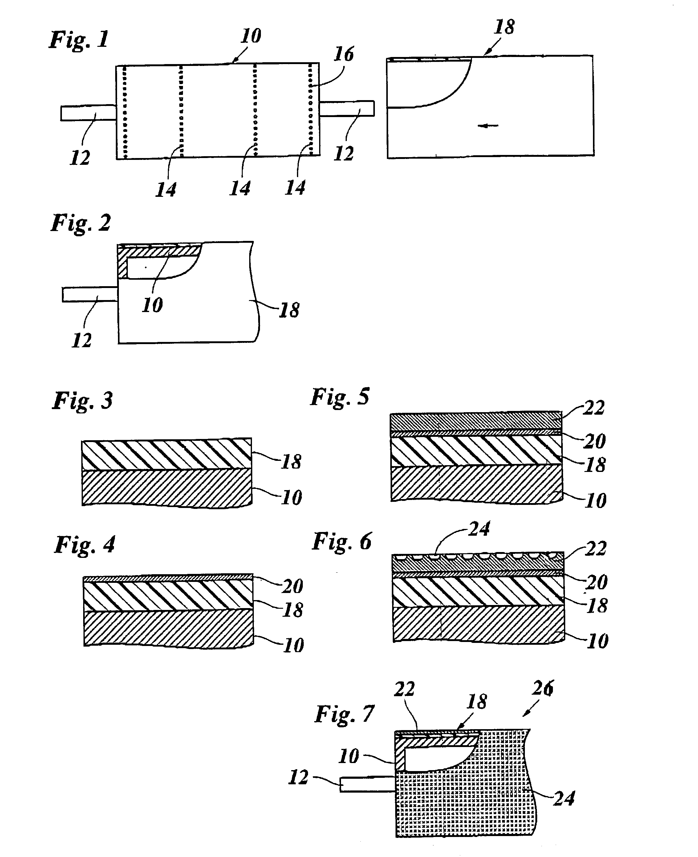
[0020] An embodiment example of the invention will now be explained in conjunction with the drawings, in which:

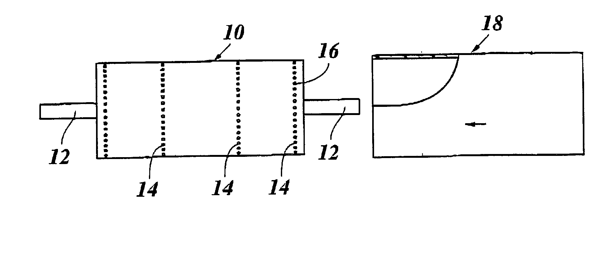
[0021] FIG. 1 a view of a core and, partly broken away, a sleeve in an initial stage of a process of manufacturing an anilox roller;

[0022] FIG. 2 a partial view of the anilox roller after the sleeve has been thrust onto the core;

[0023] FIG. 3 to 6 enlarged drawings of the layer structure of the anilox roller in different stages of the manufacturing process; and

[0024] FIG. 7a a partly broken-away view of the anilox roller obtained by the method according to the invention.

[0025] FIG. 1 shows (not on scale) a view of a core 10 of an anilox roller. The core 10 has the shape of a hollow cylinder and consists of a material which is rigid in shape and nevertheless as lightweight as possible, e.g. steel, aluminum or, preferably, carbon fiber-reinforced synthetic resin. Both ends of the core 10 are provided with bearing studs 12 which serve for supporting the anilox roller in a prin...


PUM

PropertyMeasurementUnit
Thicknessaaaaaaaaaa
Thicknessaaaaaaaaaa

Abstract

A method of manufacturing an anilox roller, in particular for a flexographic printing press, the anilox roller comprising a cylindrical core and a sleeve detachably held on the core and having at its surface an anilox layer with a grid pattern of pits, comprising the steps of mounting the sleeve on the core, and then forming the anilox layer on the sleeve

Description

[0001] 1. Field of the Invention[0002] The invention relates to a method for manufacturing an anilox roller, in particular for flexographic printing machines, the roller comprising a cylindrical core and a sleeve which is detachably held on the core and has at its surface an anilox layer with a grid pattern of pits. The invention further relates to an anilox roller manufactured according to this method and to a method of recycling the same.[0003] 2. Description of the Related Art[0004] In flexographic printing, the printing ink is applied onto an impression cylinder by means of an anilox roller. The surface of the anilox roller passes through a chamber-type doctor assembly in which the minute pits of the grid pattern are filled with ink. When, then, the anilox roller comes into contact with the impression cylinder at another location of its circumference, the ink is transferred onto the printing parts of the impression cylinder.[0005] Known anilox rollers typically have a non-deform...

Claims


Application Information

Patent Timeline
IPC IPC(8): B41F31/26
CPCB41F31/26B41N2207/02B41C1/05Y10T29/49549Y10T29/49558Y10T29/4956Y10T29/49563B41N7/06
Inventor KOLBE, WILFRIEDSCHIRRICH, KLAUSBRUSDEILINS, WOLFGANGSTEINMEIER, BODO
Owner FISCHER & KRECKE
Why Eureka
Try Eureka