Endoscope

a technology of endoscope and endoscope, which is applied in the field of endoscope, can solve the problems of complex management of disinfectant, high running cost, and equipment not being able to use immediately after sterilization, and achieve the effect of improving repairability

Inactive Publication Date: 2003-08-07
OLYMPUS CORP
View PDF1 Cites 24 Cited by
  • Summary
  • Abstract
  • Description
  • Claims
  • Application Information

AI Technical Summary

Benefits of technology

0018] It is an object of the present invention to provide an endoscope, inexpensive, in which observation performance ...

Problems solved by technology

There was a problem in that since aeration for removing gases adhered to the equipment after sterilization takes much time, the equipment is not able to use immediately after the sterilization.
Furthermore, there is a problem in that the running cost is high.
On the other hand, regarding the disinfectant, there are problems in that management of the disinfectant is complicated, and disposal of the disinfectant requires a significant cost.
General materials which do not pass the high-temperature high-pressure steam under the conditions stipulated by current US standards, etc., are limited to the materials selected from metals, ceramic, glass, and crystalline materials.
Junction devices for joining materials to each other are also limited to the junction methods, for example, soldering, in which primary component of the joint portion are metals, ceramic, glass, and crystalline materials.
However, regarding the endoscope adaptable to the high-temperature high-pressure steam sterilization of the related art example, in the case of a common steam-tight structure, steam of the high-temperature high-pressure steam sterilization may enter into the optical path between the optical members and, thereby, observation performance is adversely affected.
On the other hand, since the number of steps of steam-tight junction is increased and the operation thereof becomes complicated, it is difficult to improve ease of assembling and, as a result, the assembling cost and the manufacturing cost are increased.
Regarding the junction method, when a method of laser welding, soldering, brazing, or the like is performed, there is an inconvenience that disassembling of individual primary components became difficult and, therefore, repairability was adversely affected.
General materials, whic...

Method used


Image

  • Endoscope
  • Endoscope
  • Endoscope

Examples


first embodiment

[0045] (First Embodiment)

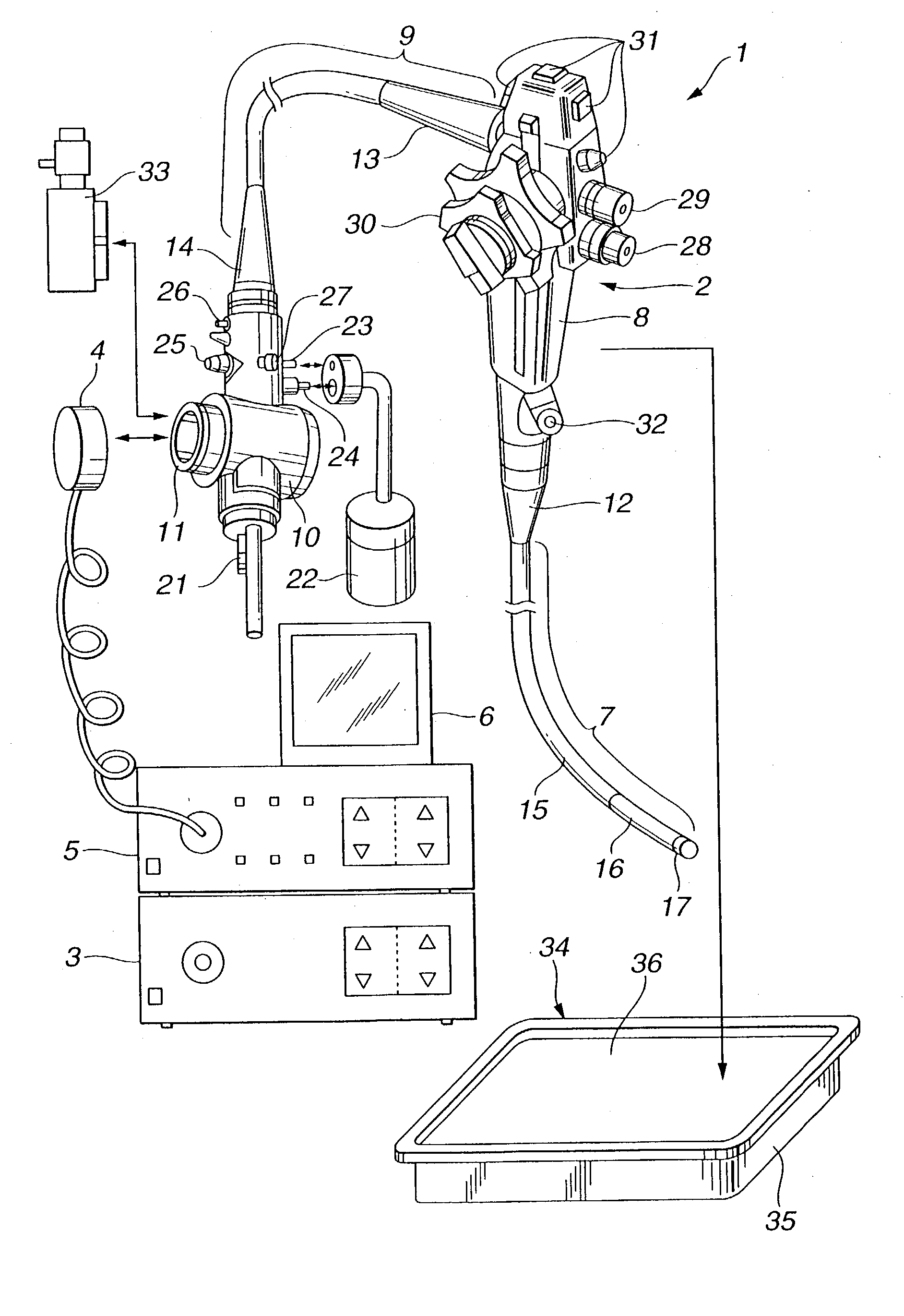
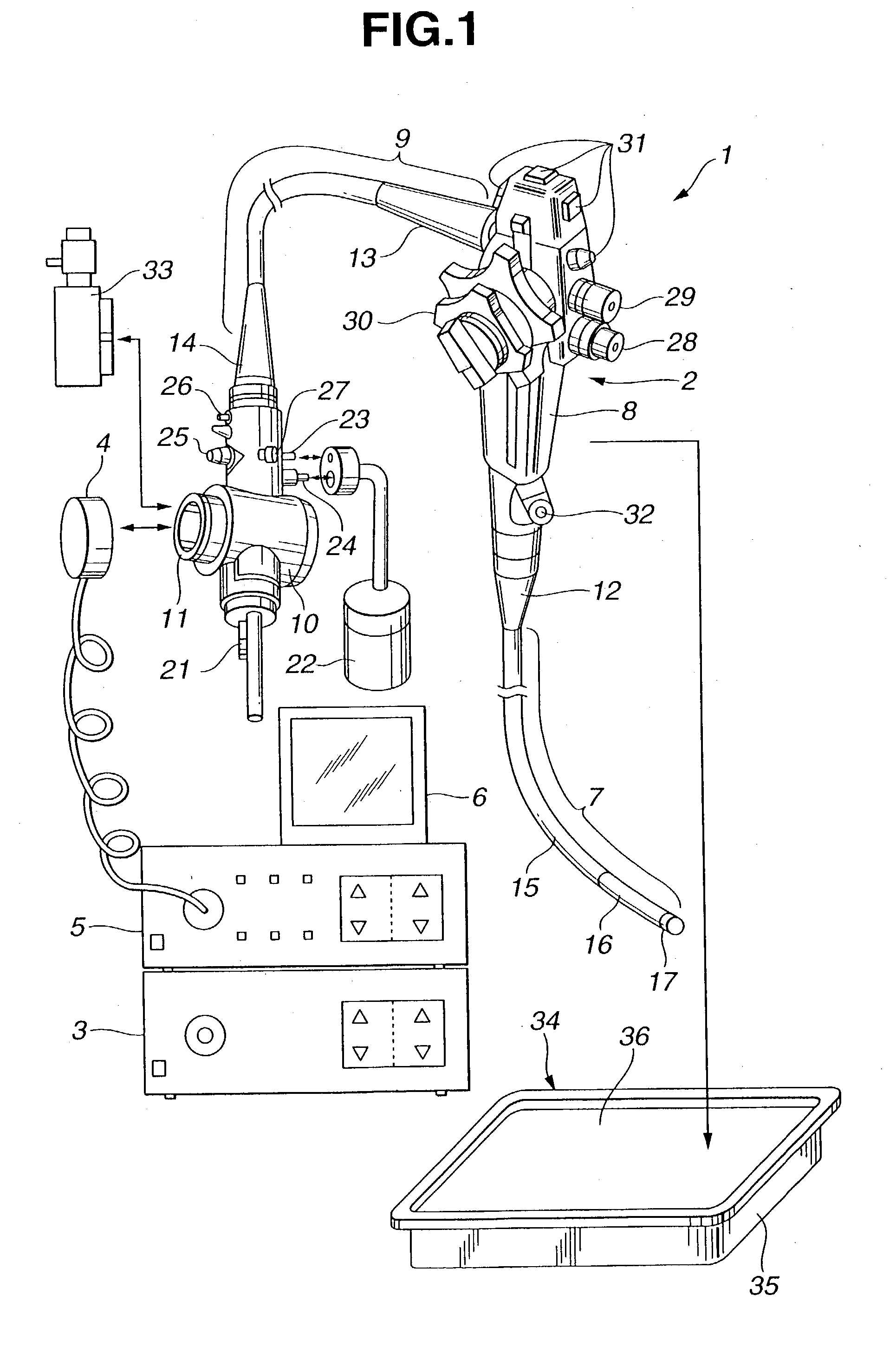
[0046] The first embodiment of the present invention will be described with reference to FIG. 1 to FIG. 5B.

[0047] Initially, the configuration thereof will be described.

[0048] As shown in FIG. 1, an endoscope apparatus 1 is configured to include an endoscope 2 of the first embodiment with built-in image pickup means, a light source device 3 which is freely detachably connected to the endoscope 2 and which supplies illumination light to a light guide (not shown in the drawing) arranged in the endoscope 2, a video processor 5 which is connected to the endoscope 2 via a signal cable 4 and which controls an image pickup means of the endoscope 2 and, in addition, processes signals obtained from the image pickup means, and a monitor 6 for displaying an image corresponding to a subject image output from the video processor 5.

[0049] The endoscope 2 is configured such that after the use for observation and therapy, cleaning is performed, and subsequently, sterilizati...

second embodiment

[0147] (Second Embodiment)

[0148] The second embodiment of the present invention will be described with reference to FIG. 6.

[0149] Initially, the configuration of the present embodiment will be described. The overall configuration of an endoscope of the present embodiment is similar to that shown in FIG. 1. FIG. 6 shows the configuration of the tip portion of the endoscope according to the second embodiment.

[0150] Although when the tip portion 17 is cooled with cool water after high-temperature high-pressure steam sterilization and when water is supplied from a gas and water supply nozzle 18 (refer to FIG. 6) by operation of the gas and water supply operation button 28 during inspection and, therefore, the illuminational optical system unit 43 is cooled, moisture in the illuminational optical system unit 43 may condense and fogging of these lenses may occur, regarding the endoscope of the present embodiment, occurrence of such fogging is prevented by arranging the water supply nozzle...

third embodiment

[0162] (Third Embodiment)

[0163] The configuration of the present embodiment will be described.

[0164] FIG. 7 is a sectional view showing the configuration of a curving-operation knob of an operating portion in the third embodiment of the present invention.

[0165] Regarding an endoscope of the present embodiment, in order to improve operability of the operating portion, the sealing member of the movable portion is formed from a material having a steam permeability that is lower than the steam permeability of a resin constituting the integument of the flexible tube of the insertion portion.

[0166] As shown in FIG. 7, a fixed axis 58 is fitted into a penetration hole 56 of an operating portion casing 55 of the operating portion 8. This fixed axis 58 is arranged in the operating portion 8, and is fixed to an operating portion chassis 57 fixed to the operating portion 8.

[0167] An O-ring 64a as a sealing member is arranged between the penetration hole 56 and the fixed axis 58.

[0168] A curvin...


PUM


Abstract

An illuminational optical system and an observational optical system mounted to lens frames are arranged at the tip part of an insertion portion. The observational optical system has resistance to high-temperature steam sterilization, and is sealed steam-tight in order to avoid entering of steam into the inside. On the other hand, the illuminational optical system is sealed liquid-tight with an adhesive, and even when steam enters into the inside, the entered steam can be discharged by the heat accompanying illumination light during an endoscope inspection. Consequently, cost reduction can be achieved and repairability, etc., can be ensured with almost no degradation in observation performance.

Description

[0001] This application claims benefit of Japanese Patent Application No. 2001-358029 filed on Nov. 22, 2001, the contents of which are incorporated by this reference.[0002] Field of the Invention and Description of the Related Art[0003] The present invention relates to an endoscope adaptable to high-temperature high-pressure steam sterilization primarily used for medical application. In particular, the present invention relates to an endoscope, inexpensive, in which observation performance is not degraded even when high-temperature high-pressure steam sterilization is performed, and repairability, moisture resistance, durability, and operability can be improved.[0004] Conventionally, regarding endoscopes widely used for medical application, observation of organs in the body cavity, etc., can be performed and, if necessary, various therapies and treatments can be performed using a slender insertion portion of therapeutic instruments being inserted through the therapeutic instrument ...

Claims


Application Information

Patent Timeline
IPC IPC(8): G02B23/24A61B1/00A61B1/05
CPCA61B1/05A61B1/00096
Inventor ISHIBIKI, KOTA
Owner OLYMPUS CORP
Why Eureka
Try Eureka