Multi-path split cell spacer and electrodialysis stack design

a split cell spacer and electrodialysis technology, applied in the direction of liquid/fluent solid measurement, fluid pressure measurement, peptide, etc., can solve the problems of inability to consistently and economically produce a cleansed fluid of sufficient quality that can be continuously recycled, prohibiting cost-effective recycling for environmental compliance or beneficial reuse, and many of the systems purchased by many businesses

Inactive Publication Date: 2003-08-21
EET TN
View PDF11 Cites 58 Cited by
  • Summary
  • Abstract
  • Description
  • Claims
  • Application Information

AI Technical Summary

Problems solved by technology

Present state of the art systems, including de-ionization methods that are available to industrial waste stream generators, are deficient in their ability to consistently and economically produce a cleansed fluid of sufficient quality that can be continuously recycled and reused, especially in the case of small to medium volume liquid waste generation.
The initial high cost of purchasing many of these systems is beyond the economic resources of many businesses, thus prohibiting cost-effective recycling for environmental compliance or beneficial reuse.
The most serious design problem for both flow arrangements for multi-membrane and multi-cell stacks is that of assuring uniform fluid flow to the various compartments and effective transport of the ions to the membrane surfaces.
These difficulties are the major obstacles to simple, single stage demineralization of brackish liquids.
In particular, reducing concentration polarization is one of the most important design issues for electrodialysis.
This water splitting is extremely detrimental to electrodialysis efficiency.
Polarization is objectionable not only from the standpoint of the inefficient increase in energy consumption, but also the change of pH of the concentrate stream as a result of water splitting, which tends to cause scale deposition.
The number of cells in a stack is limited mainly by the practical considerations of assembly and maintenance requirements.
Since the failure of a single membrane can seriously impair stack performance, the necessity to be able to disassemble and reassemble a stack to replace a membrane, and the necessity to be able to perform this quickly and easily, effectively limits the number of membranes that can be practically utilized in a stack.
However, use of single electrodes for larger assemblies typically causes end-cell heating that results in rapid membrane deterioration.

Method used


Image

  • Multi-path split cell spacer and electrodialysis stack design
  • Multi-path split cell spacer and electrodialysis stack design
  • Multi-path split cell spacer and electrodialysis stack design

Examples


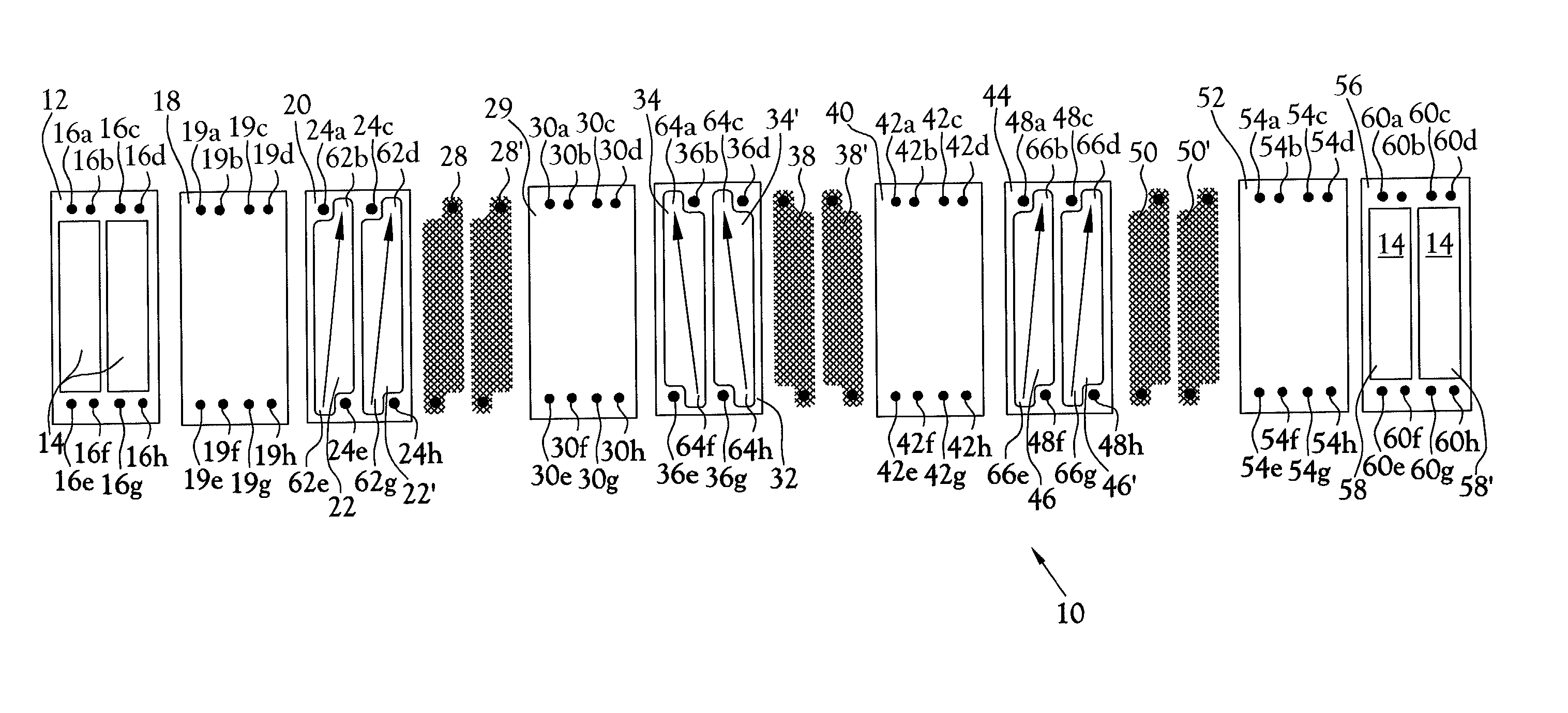
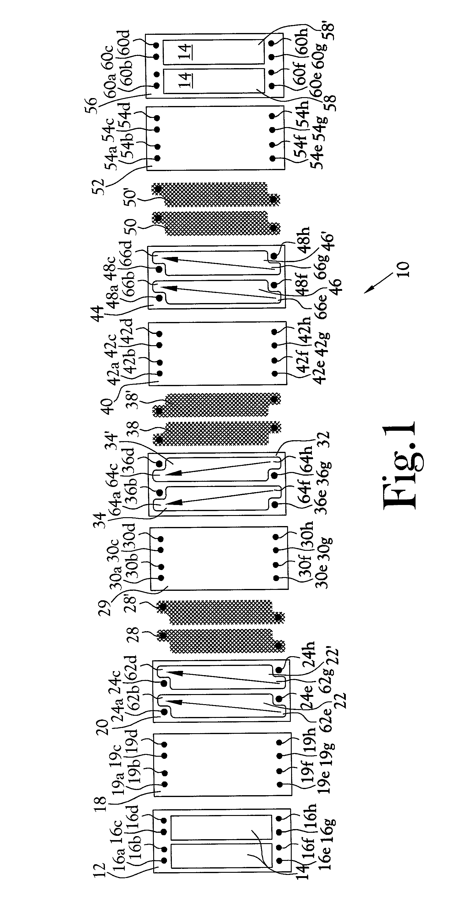
Embodiment Construction

shows the production rate and typical % removal of NaCl for the current invention; those skilled in the art will recognize these values allow the invention to be economically competitive for a variety of feeds. Example 3 shows typical membrane area and energy requirements for desalination using traditional ED stack designs contrasted with the performance of the current invention. Those skilled in the art will recognize that the improved design of the current invention results in a stack requiring significantly less membrane area and that is significantly more energy efficient.

2 1. NaCl Feed Production Rate % NaCl Concentration (m.sup.3 / m.sup.2 day) Removal 1.65 g / L 5.74 91 16.5 g / L 1.50 99

[0064]

3 NaCl Feed Traditional % Concentration Designs** Split cell Reduction A. Membrane Area (m.sup.2) for 1 m.sup.3 / day Capacity* 1 g / L 0.3 0.17 42% 10 g / L 1.2 0.67 44% B. Energy Requirements (kw-hr / m.sup.3 product)* 1 g / L 1.2 0.26 78% 10 g / L 3.4 2.67 21% *For a product concentration of 500 ppm T...


PUM

PropertyMeasurementUnit
sizesaaaaaaaaaa
sizesaaaaaaaaaa
electrically conductiveaaaaaaaaaa

Abstract

An electrodialysis method and apparatus include a source of concentrate fluid, a source of dilute fluid, a collector of treated concentrate fluid, a collector of dilute fluid, an anode and a cathode. A plurality of generally planar spacers are interleaved with a plurality of membranes to define a plurality of cells providing electrically conductive fluid connection between the anode and the cathode. Each of the spacers comprises a gasket that defines a first aperture and a second aperture. Each of said first and second apertures define an independent cell between interleaved membranes. The symmetrical, multiple split cell spacer configuration channels fluid flow through two or more narrow and elongated paths. The split cell arrangement allows for operation of the stack in parallel or in series. The invention improves the ion removal efficiency of a given membrane area, requires significantly less energy than other electrodialysis systems and substantially reduces stack assembly, materials and fabrication costs.

Description

[0001] Not Applicable[0002] Not Applicable[0003] 1. Field of Invention[0004] This invention pertains to a method and apparatus for the purification and reuse or disposal of polluted liquids.[0005] More particularly, this invention pertains to an electrodialysis stack for the removal and concentration of ions from aqueous solutions and certain aqueous / organic solutions.[0006] 2. Description of the Related Art[0007] There are presently a number of systems for treating and recycling aqueous and aqueous / organic waste streams on the market. Present state of the art systems, including de-ionization methods that are available to industrial waste stream generators, are deficient in their ability to consistently and economically produce a cleansed fluid of sufficient quality that can be continuously recycled and reused, especially in the case of small to medium volume liquid waste generation. The initial high cost of purchasing many of these systems is beyond the economic resources of many b...

Claims


Application Information

Patent Timeline
Patent Type & Authority Applications(United States)
IPC IPC(8): B01D61/46B01D61/50B01D63/08C02F1/469
CPCB01D61/50B01D63/084B01D2313/345B01D2313/14C02F1/4693Y02A20/124Y02A20/131
Inventor SFERRAZZA, ALOIS
Owner EET TN
Why Eureka
Try Eureka