Pentagonal helical antenna array

a technology of helical antenna array and tail section, which is applied in the direction of individually energised antenna array, electrical apparatus, structural forms of radiation elements, etc., can solve the problems of limiting the size of antennas that can be placed in this tail section, limiting the gain of antennas, and unsatisfactory preferred polygon configuration

Inactive Publication Date: 2003-09-04
EMS TECH CANADA
View PDF6 Cites 42 Cited by
  • Summary
  • Abstract
  • Description
  • Claims
  • Application Information

AI Technical Summary

Benefits of technology

[0009] The present invention provides a pentagonal antenna array having a high aperture efficiency and a suitably high overall gain and low antenna noise temperature. The high aperture efficiency of this antenna system provides an overall system capacity suitable for broadband communication services. The antenna array consists of five antenna elements each located at a separate vertex of a pentagon. The antenna elements are helical antennas to provide a narrow antenna beam width. The antenna array itself is supported on a base platter which may be steered to point at a satellite using conventional gimbal ring apparatus. The base platter is a planar reflector to reflect the antenna element radiation in the rear direction and thereby reduce the antenna backlobe levels. The input power and the signal transmitted are fed through a phasing / combining network. The phasing / combining network appropriately divides the signal and the input power and phases the signal, prior to feeding the signal to each of the five antenna elements.
[0010] The antenna elements are positioned at the points of a pentagon, which are 72.degree. apart, around the antenna base. Adjacent elements have a 72.degree. relative angular rotation and a compensating 72.degree. relative excitation phase in order to ensure that the elements are all radiating in phase, which results in very uniform excitation of the entire volume of the antenna and the elimination of polarisation loss. Each helical antenna element launches an axial wave that is circularly polarised. The individual helices are angularly displaced 72.degree. and the phase of the current provided to the windings is sequentially offset by 72.degree. such that the radiated fields are in phase. This sequential "displacement" virtually eliminated polarisation loss by avoiding the alignment of the principal axes of the individual polarisation ellipses. The individual helices positioning is arranged that each one has a direction 72.degree. from the position of its neighbours. If they were fed in phase their radiated signals would be out of phase. But by feeding them 72.degree. from their neighbours their radiated signals are in phase.

Problems solved by technology

Modern aircraft travel through great distances, often over open water and far from the reach of most conventional communications services.
The tail sections of modern aircraft tend to be very narrow and, consequently, there is a limit to the size of antenna that can be placed in this tail section.
However, one shortcoming of Hines is that the preferred polygon configuration is not ideal for satellite antenna applications where aperture efficiency is critical for providing communication services.
Furthermore, the antenna elements described by Hines have a very broad beam width thus limiting the antenna's gain.
The broad beam width, however, is a hindrance in satellite applications where the maximum gain possible is required.

Method used


Image

  • Pentagonal helical antenna array
  • Pentagonal helical antenna array
  • Pentagonal helical antenna array

Examples


Embodiment Construction

:

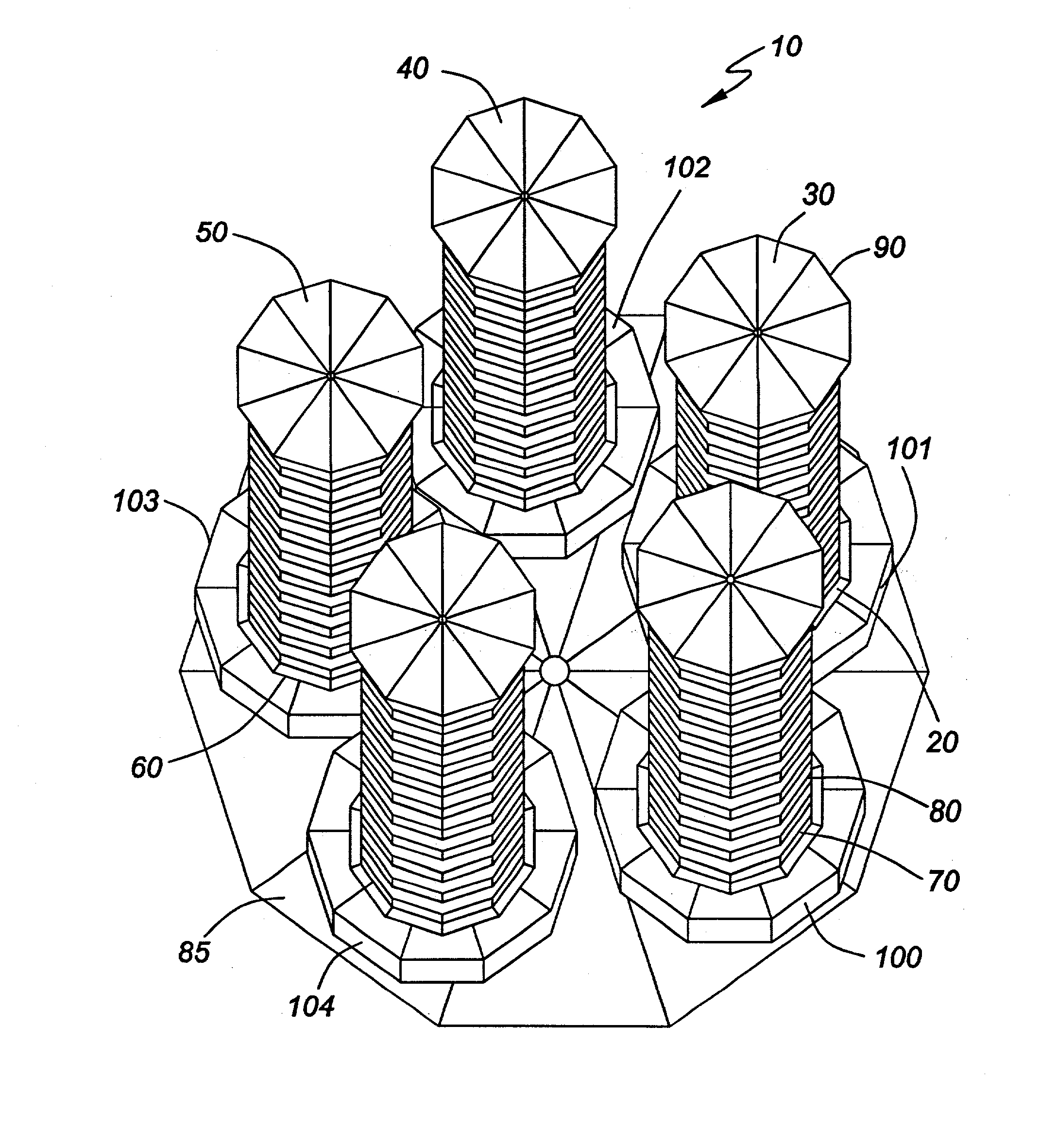
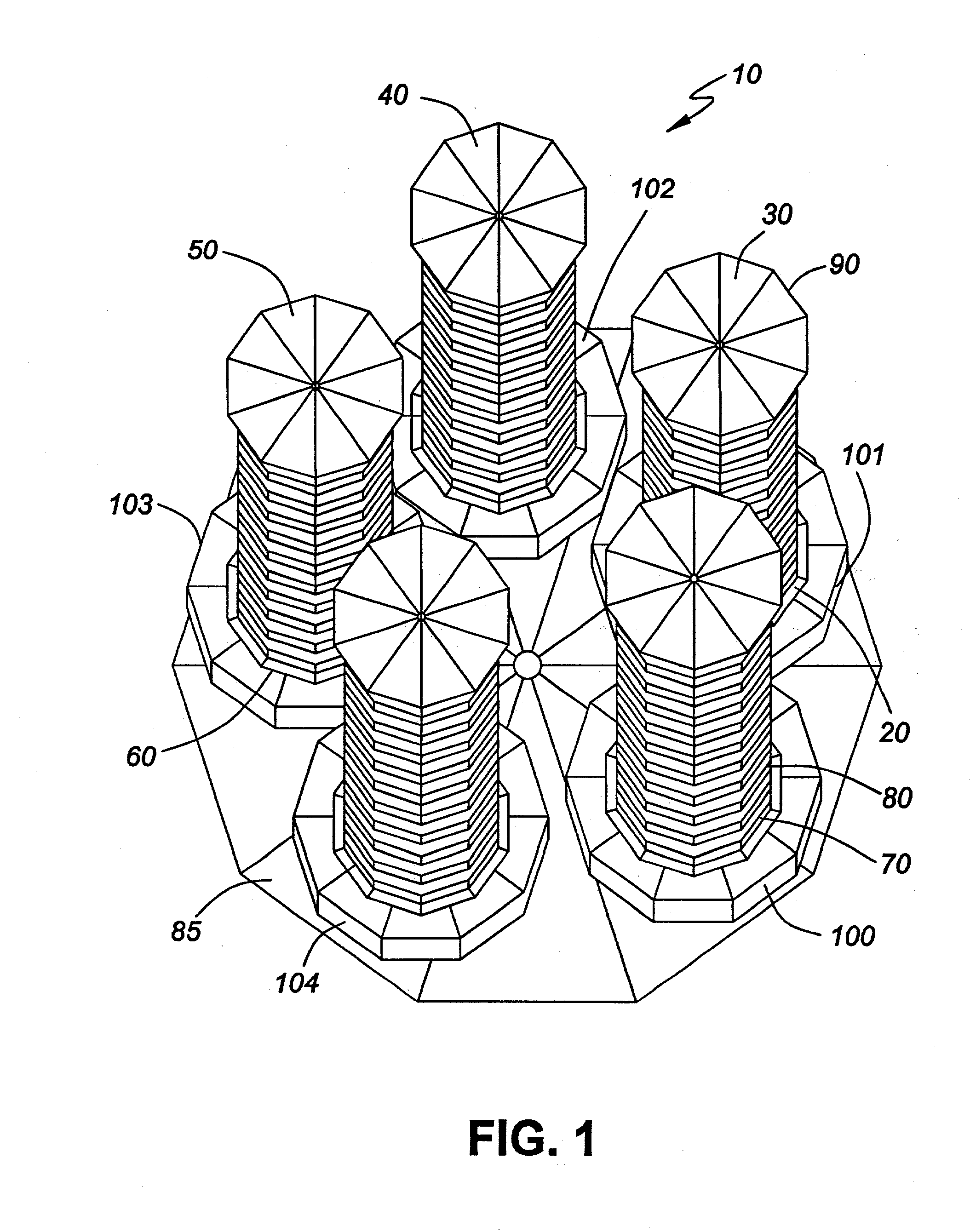
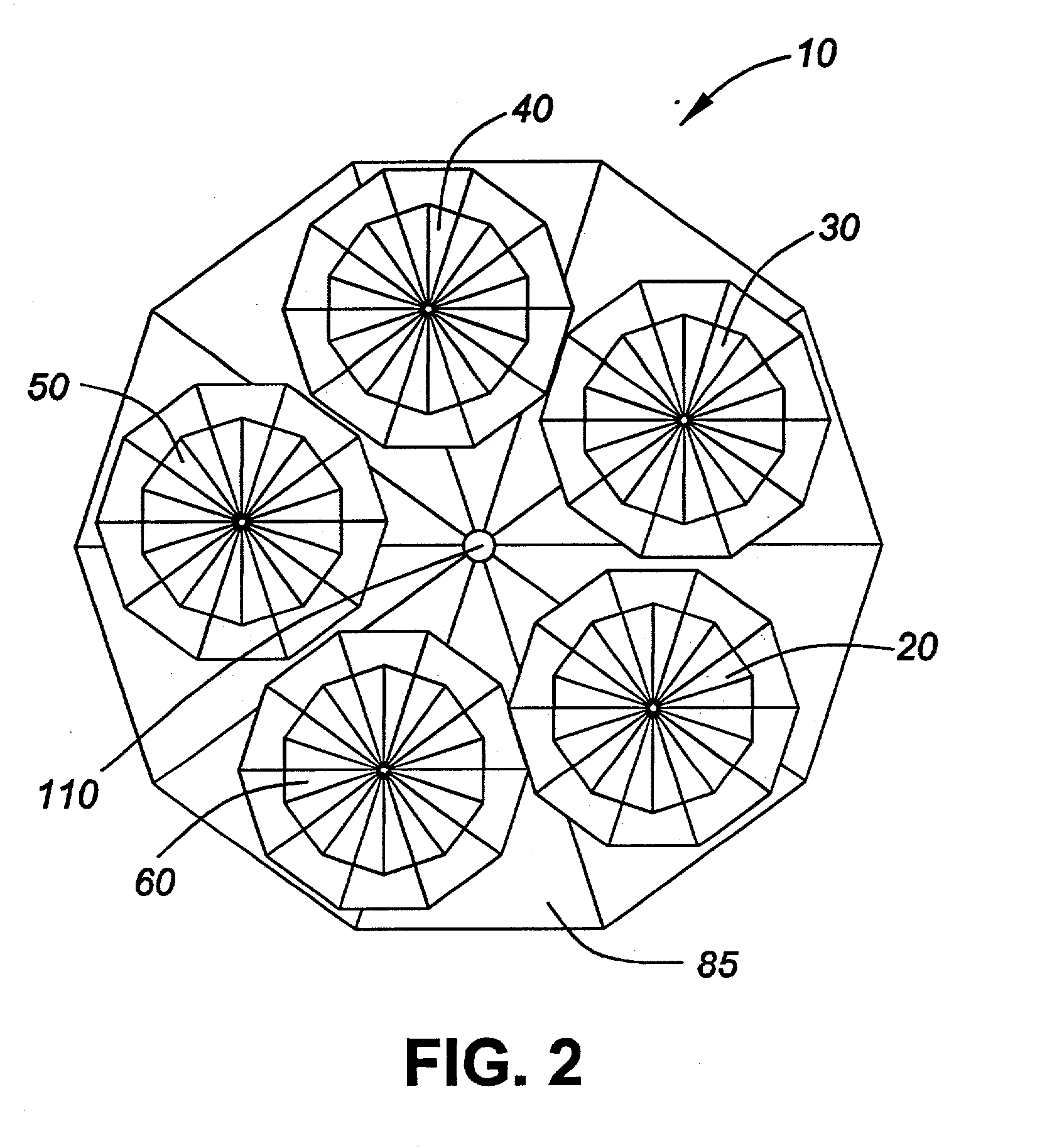
[0035] FIGS. 1-4 are the various views of a pentagonal antenna array according to one embodiment of the present invention.

[0036] FIG. 1 illustrates an isometric view of the antenna system 10. The antenna elements shown are five mono-filar helical antenna elements, 20, 30, 40, 50, 60. A mono-filar helical antenna element consists of a conductive filament helically wound around a support structure 80. The support structure shown is a cylindrical non-conducting tube but other suitable support structure designs are possible. As can be seen in FIG. 1, each mono-filar helical antenna element is identical. The element 20 has a conductive filament 70 that is wound around the support structure 80. A better illustration of the support structure is shown in FIG. 4. At the base end of the support structure there is a base end of the conductive filament 70 where current is fed. The filament 70 has its own feed (not shown) which is a conductive element, such as electrical wire or strip. Each fil...


PUM


Abstract

A pentagonal antenna array having a high aperture efficiency and a suitably high overall gain and low antenna noise temperature. The high aperture efficiency of this antenna system provides an overall system capacity suitable for broadband communication services. The antenna. array consists of five antenna elements each located at a separate vertex of a pentagon. The antenna elements are helical antennas to provide a narrow antenna beam width. The antenna array itself is supported on a base platter which may be steered to point at a satellite using conventional gimbal ring apparatus. The base platter is a planar reflector to reflect the antenna element radiation in the rear direction and thereby reduce the antenna backlobe levels. The input power and the signal transmitted are fed through a phasing / combining network. The phasing / combining network appropriately divides the signal and the input power and phases the signal, prior to feeding the signal to each of the five antenna elements.

Description

[0001] The present invention relates to a phased-array antenna for both ground and airborne satellite communications. More particularly, the invention relates to such an array of antenna elements which are disposed in a pentagonal configuration.BACKGROUND TO THE INVENTION[0002] Modern aircraft travel through great distances, often over open water and far from the reach of most conventional communications services. Satellite communications have become crucial to pilots when navigating an aircraft, receiving weather reports and air traffic control information, as well as communicating status and emergency messages. Satellite communication systems located on aircraft provides a means for communication while the aircraft is airborne or on the ground. In addition, satellite communication systems are useful in providing such services as telephone communication, Internet services, and other forms of data exchange to the aircraft passengers. In order to provide these additional services to ...

Claims


Application Information

Patent Timeline
Patent Type & Authority Applications(United States)
IPC IPC(8): H01Q21/06
CPCH01Q21/067
Inventor STRICKLAND, PETER C.
Owner EMS TECH CANADA
Why Eureka
Try Eureka