
Anti-fogging element and method for forming the same

a technology of anti-fogging elements and methods, applied in the direction of optical elements, physical/chemical process catalysts, instruments, etc., can solve the problems of affecting the photocatalytic property, increasing the cost of production, and complicating the process

Inactive Publication Date: 2003-09-25
MURAKAMI CORP
View PDF4 Cites 11 Cited by
  • Summary
  • Abstract
  • Description
  • Claims
  • Application Information

AI Technical Summary

Problems solved by technology

However, in the case where the anti-fog element suggested by the applicant is formed by the application of the technique disclosed in International Patent Publication WO96 / 29375 mentioned above, the following problems are posed.
First, if an amorphous titanium dioxide TiO.sub.2 film is formed on a glass containing an alkali such as a soda lime glass and sintered at a temperature of 400.degree. C. to 500.degree. C., the alkali component contained in the glass would be diffused into the TiO.sub.2 film, impairing the photocatalytic property.
Consequently, a film for preventing the diffusion should be formed between the TiO.sub.2 film and the glass, complicating the processes and leading to higher expenses.
Second, even if the TiO.sub.2 film is formed onto a mirror (a substrate which already possesses a reflecting film), the TiO.sub.2 film must be sintered at a temperature of 400.degree. C. to 500.degree. C. and, thus, the metal film which is the reflecting film undergoes oxidation, impairing the reflecting ratio.
Consequently, in the course of the fabrication of the anti-fog element, any alkaline substance is difficult to be dispersed into the photocatalyzer film and, thus, even if a soda lime glass is used as the substrate, no film for preventing the alkali dispersion is required.
Due to the treatment at a low temperature, it is difficult for the reflecting film to be oxidized, not impairing the reflecting ratio.

Method used


Image

  • Anti-fogging element and method for forming the same
  • Anti-fogging element and method for forming the same
  • Anti-fogging element and method for forming the same

Examples


example 1

(1) Example 1

[0041] (FIG. 7)

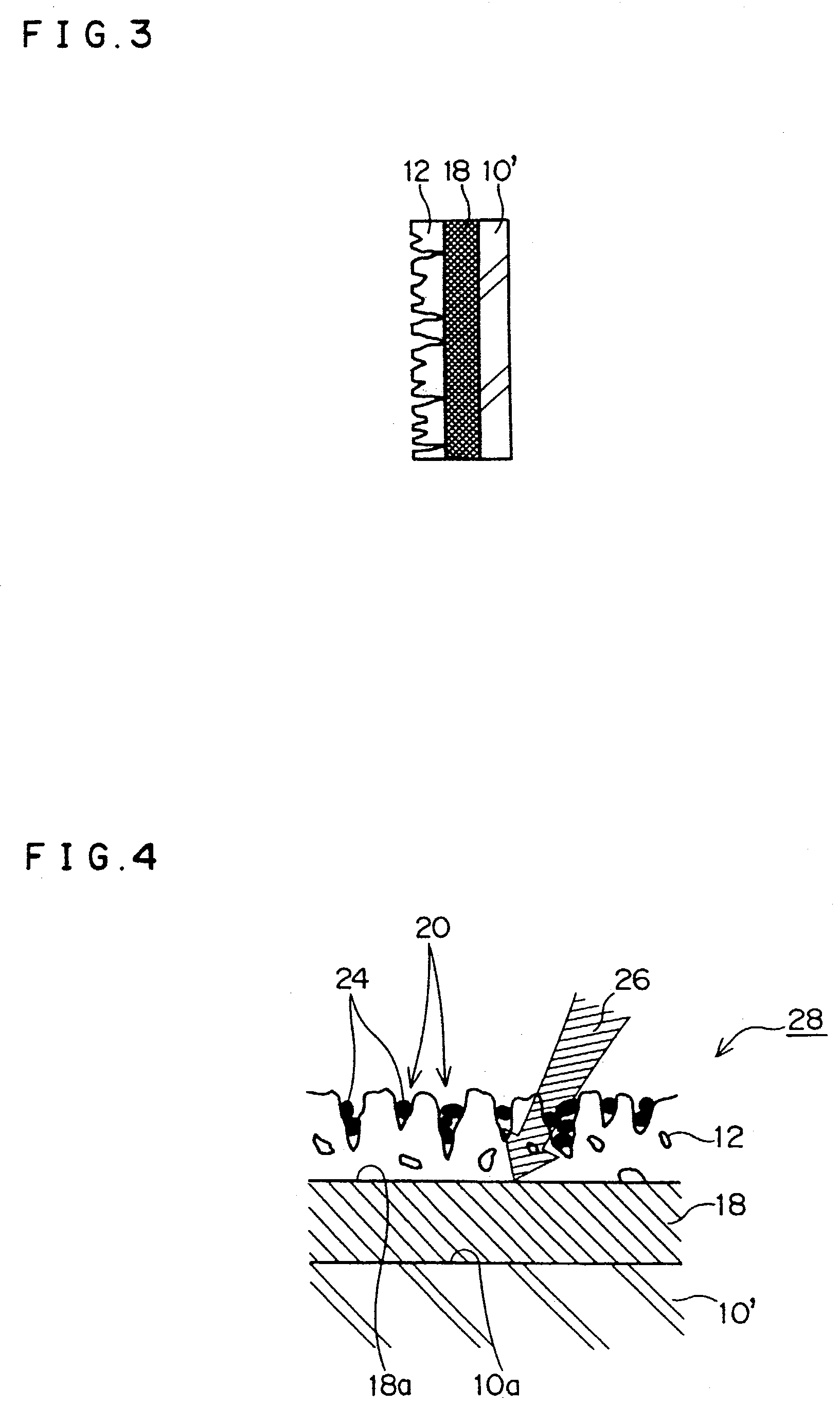
[0042] An automobile outer mirror 30 is configured as a door mirror or a fender mirror. The outer mirror 30 possesses a mirror body 32 having a mirror assembly 34 accommodated therein. The mirror assembly 34 is composed of a transparent glass substrate 10 having a TiO.sub.2 film 18 and a porous SiO.sub.2 film 12 formed on the front surface of the glass substrate 10, and a reflecting film 36 such as Cr or Al film formed on the rear surface of the glass substrate 10. The image behind the automobile penetrates through the SiO.sub.2 film 12, the TiO.sub.2 film 18 and the transparent glass substrate 10, and is reflected upon the reflecting film 36 to be led to the driver's eye via a reverse path. Organic substances etc., entering into the openings of the pores of the SiO.sub.2 film 12 and then adhered therein are decomposed by the oxidation-reduction reaction cause by the photocatalytic reaction on the TiO.sub.2 film 18.

example 2

(2) Example 2

[0043] (FIG. 8)

[0044] A mirror assembly 40 of an automobile outer mirror 30 is composed of a transparent glass substrate 10 having a TiO.sub.2 film 18 and a porous SiO.sub.2 film 12 formed on the front surface of the glass substrate 10, and a reflecting film 36 such as Cr or Al film formed on the rear surface of the glass substrate 10. Over substantially the entire area of the rear surface of the reflecting film 36, a panel-like heater 42 is bonded by mean of an adhesive or a bonding agent. Current is supplied to the panel-like heater from a power source 44. If the panel-like heater 40 comprises, for example, a PTC (positive characteristic thermister) panel heater, it can be directly driven by an automobile battery and, thus, no temperature control circuit or the like is required. The PTC panel heater is composed of a polymeric sheet-like heating element having PCT characteristics imparted thereto (for example, electrically conductive resin in which electrodes made of e...

example 3

(3) Example 3

[0045] (FIG. 9)

[0046] A mirror assembly 48 of an automobile outer mirror 46 is composed of a transparent glass substrate 10 having a transparent electrode film 50 such as ITO as a heating element, a TiO.sub.2 film 18 and a porous SiO.sub.2 film 12 formed on the front surface of the glass substrate 10 in this order, and a reflecting film 36 such as Cr or Al film formed on the rear surface of the glass substrate 10. Clip electrodes 54 and 56 are mounted in the upper and lower portions of the laminated transparent glass substrate 10 and the transparent electrode film 50. By supplying current from a power source 44 to the transparent electrode film 50, the transparent electrode 50 is heated to effectively remove the water droplets spread over the SiO.sub.2 film 12 in a thin film state.


PUM

PropertyMeasurementUnit
temperatureaaaaaaaaaa

Abstract

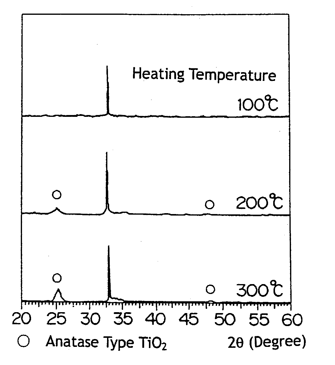
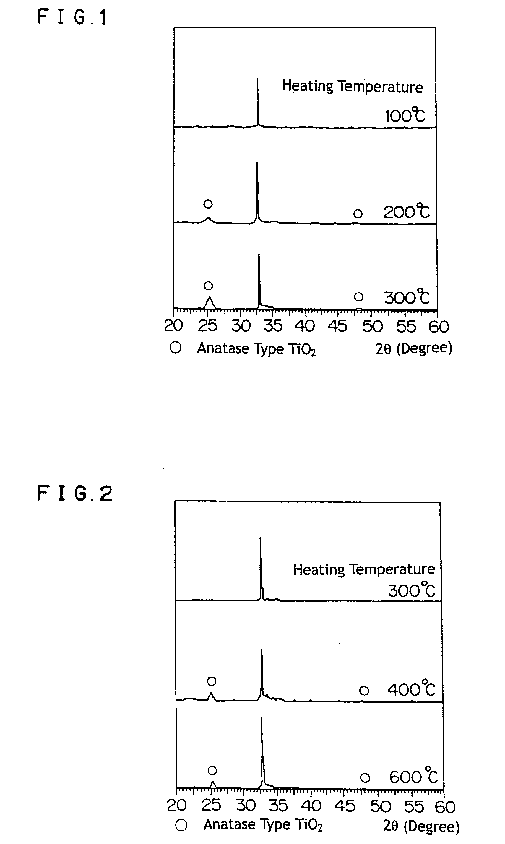
In an anti-fog element comprising a substrate, a photocatalyzer film formed on the surface of the substrate, and a porous hydrophilic film formed thereon, and a process for forming the same, a titanium peroxide solution obtainable by causing a titanium peroxide gel (orthotitanic acid) to act with hydrogen peroxide is used as a material for the photocatalyzer film. When the titanium peroxide solution is used to form a photocatalyzer film, an anatase type titanium dioxide film can be obtained at a low temperature, for example, of 200° C. Consequently, in the course of the fabrication of the anti-fog element, any alkaline substance is difficult to be dispersed into the photocatalyzer film and, thus, even if a soda lime glass is used as the substrate, no film for preventing the alkali dispersion is required. For this reason, no photocatalytic property is impaired even if no film for preventing the alkali dispersion is provided. Due to the treatment at a low temperature, it is difficult for the reflecting film to be oxidized, not impairing the reflecting ratio. What is more, the treatment at a low temperature saves energy and reduces the cost, leading decreased cost.

Description

[0001] This invention relates to an anti-fog element comprising a substrate, a film of photocatalyzer catalyzing a photocatalytic reaction formed on the surface of the substrate, and a porous hydrophilic substance film formed on the surface of the photocatalyzer film, and to a process for forming the anti-fog element. Particularly, it relates to an anti-fog element, in which an alkaline component in a glass substrate is difficult to be diffused into a photocatalyzer film, and a metal film, which is a reflective film, and is also difficult to be oxidized whereby an anatase type titanium dioxide film, which comprises a photocatalyzer, can be made at a low temperature, e.g., 200.degree. C., and a process for forming the same.BACKGROUND ARTS[0002] International Patent Publication WO96 / 29375 discloses the sintering of an organic titanium compound such as a titanium alkoxide, or an inorganic titanium compound such as TiCl.sub.4 or Ti(SO.sub.4).sub.2, at a temperature of from 400 to 500.de...

Claims


Application Information

Patent Timeline
Patent Type & Authority Applications(United States)
IPC IPC(8): A47G1/02B01J21/06B01J35/00C03C17/34C09D1/00G02B1/10
CPCA47G1/02B01J21/063B01J35/004C03C17/3411G02B1/105C03C2217/425C03C2217/71C09D1/00C03C17/3417G02B27/0006B01J35/39G02B1/18
Inventor KOBAYASHI, MASAKIKUZUYA, NORIHIKO
Owner MURAKAMI CORP
Learn More