Tubular handling apparatus and method

a tubular and handling technology, applied in the field of tubular handling apparatus and method, can solve the problems of inconvenient pipe-handling operations, increased labor intensity, and increased labor intensity of a single rig, so as to eliminate or minimize the need for time-costing manual labor, save time and labor intensity, and save tim

Inactive Publication Date: 2003-10-23
N I ENERGY DEV
View PDF69 Cites 63 Cited by
  • Summary
  • Abstract
  • Description
  • Claims
  • Application Information

AI Technical Summary

Benefits of technology

0023] The embodiments thus provide a pipe handling system for a drilling rig that provides for a safer work environment than that of a conventional rig. The system also delivers significant cost savings derived from transporting drill pipe to and from a pipe storage area automaticall

Problems solved by technology

With most if not all known drilling rigs, these pipe-handling operations cannot be conveniently performed using the rig's main hoist, because the main hoist typically is centered over the well hole, and cannot be moved laterally.
Multiple-joint rigs have significant disadvantages, however.
Because of the increased height, the mast will obviously be heavier and therefore more expensive than a shorter mast, even though the maximum hoisting loads that the mast must be designed for might be the same in either case.
A taller mast's weight and cost will be even further increased by the need to design it for increased wind loads resulting from the mast's larger lateral profile.
The larger the size of the base, or "footprint", the greater the overall cost of the well.
Tall, heavy rigs also have particular drawbacks when used on ocean-going drill platforms or drill ships.
Every extra pound of rig weight adds to the dead weight and reduces the usable load capacity correspondingly.
Extra dead weight not only increases fuel costs for transportation, but also increases expenses for supply ships, which must make more frequent visits because the platform or drill ship has less available load capacity for storage of supplies.
In storm

Method used


Image

  • Tubular handling apparatus and method
  • Tubular handling apparatus and method
  • Tubular handling apparatus and method

Examples


Embodiment Construction

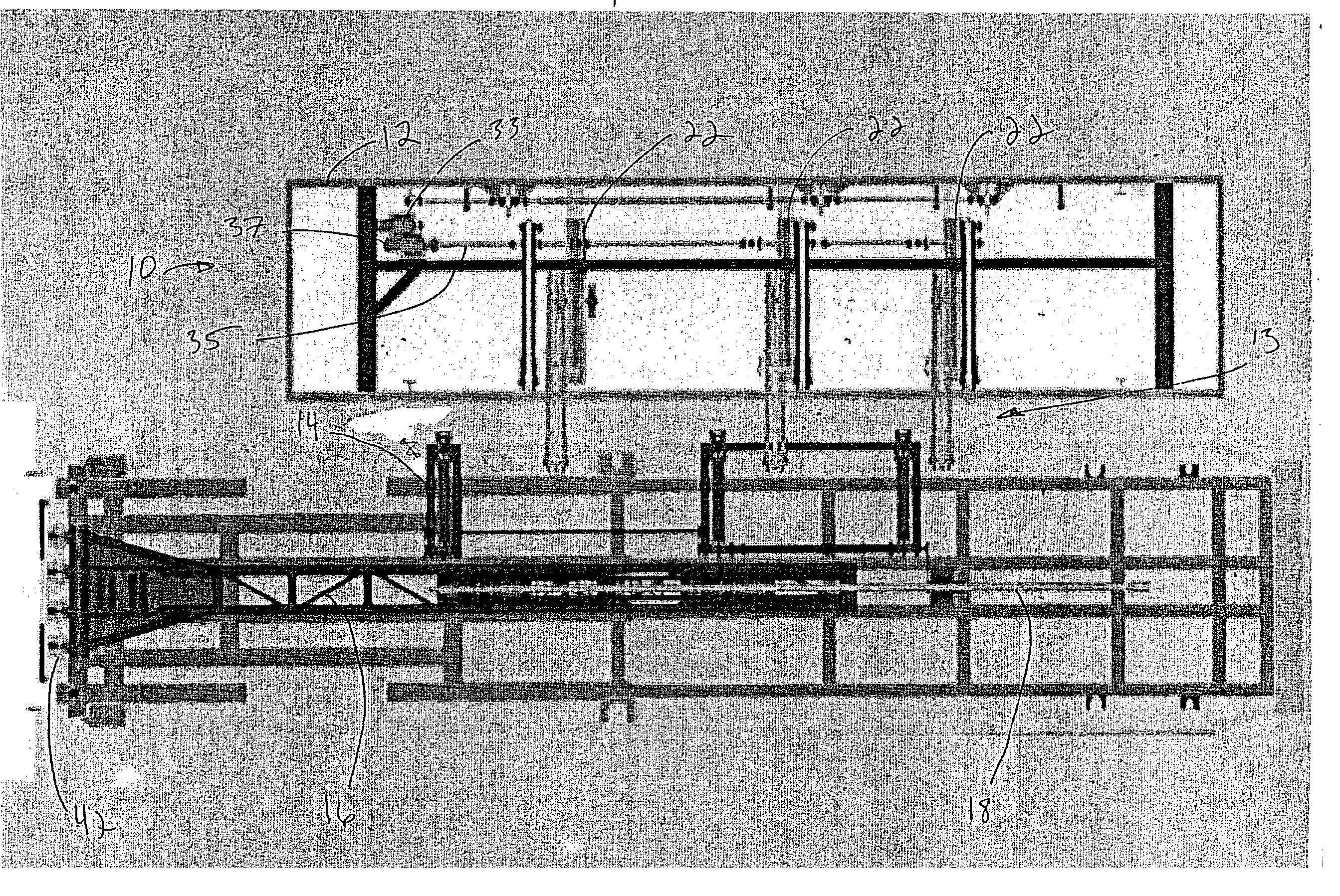
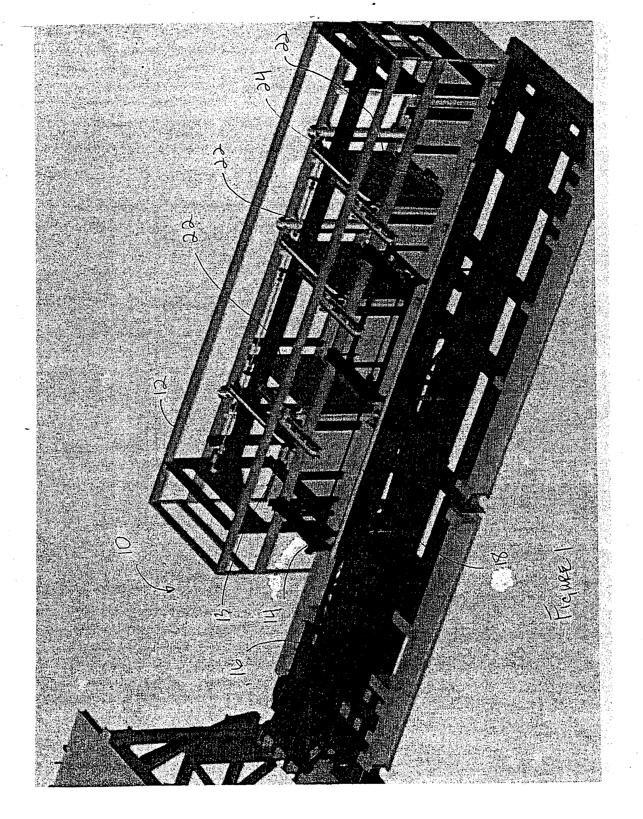
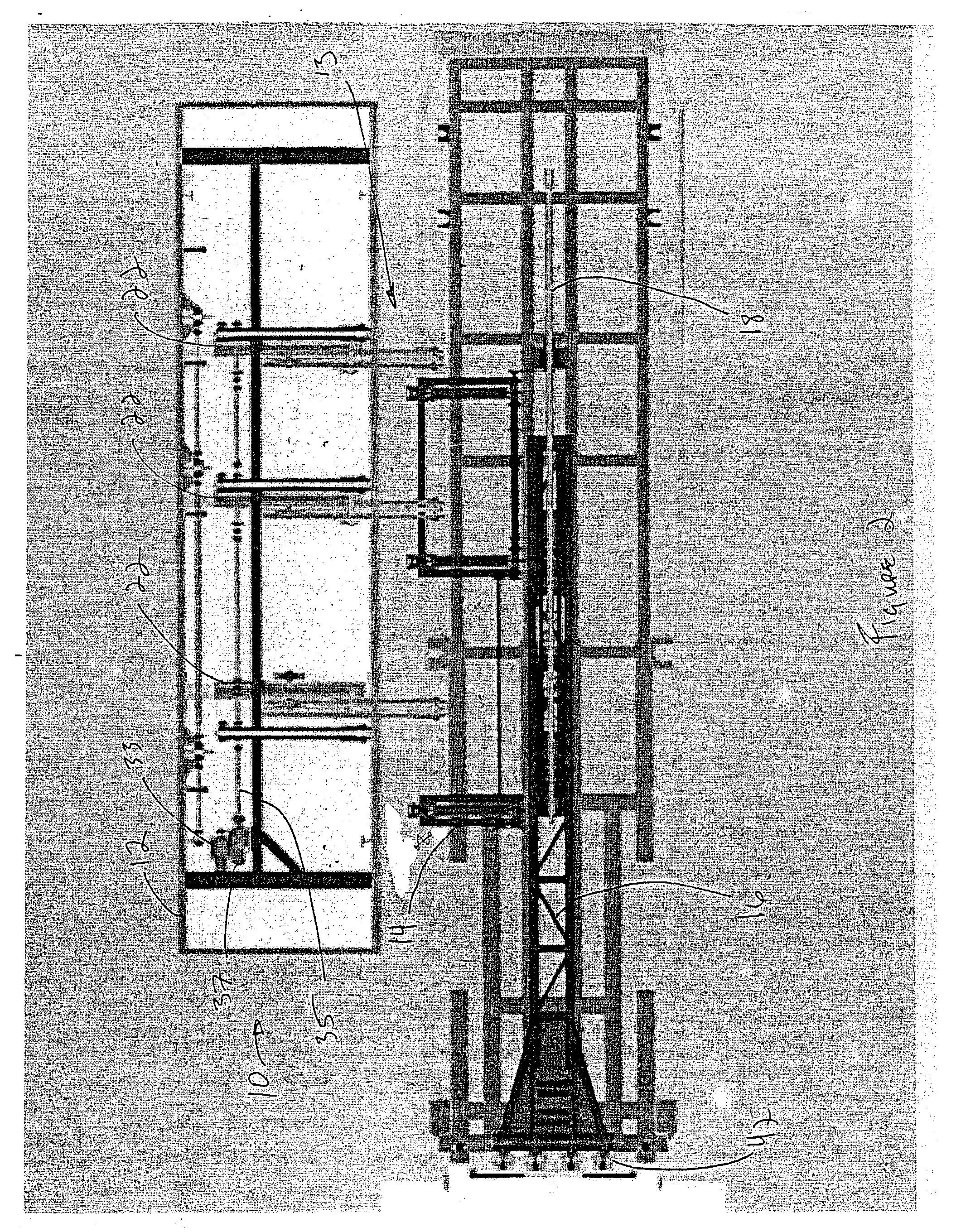
[0018] In one embodiment, the pipe handling system comprises a pipe magazine, a pipe conveyor system, and a pipe arm for use in automatically handling pipes in conjunction with a drill rig for drilling a well bore. Alternatively, the pipe handling system includes multiple pipe magazines, each with conveyor systems that transport the pipe from one pipe magazine to another until the pipe is delivered to the pipe arm.

[0019] In operation, the pipe handling system runs in two modes, RIH mode where pipe is delivered from the magazine and POH mode where pipe is delivered to the magazine.

[0020] In the RIH mode, the pipe magazine delivers joints of pipe to the pipe conveyor system. The pipe conveyor system receives the joint of pipe from the magazine and then delivers the joint of pipe to the pipe arm. Clamps on the pipe arm then clamp around the pipe joint and hold it as the pipe arm pivots from a horizontal position to a vertical position. The pipe arm then presents the pipe joint over the...


PUM


Abstract

A pipe handling system comprising at least one pipe magazine, a pipe conveyor system, and a pipe arm for handling pipes in conjunction with a drill rig for drilling a well bore. The pipe handling system operates to transfer pipe joints from each pipe magazine to a pipe arm via the pipe conveyor system. The pipe arm then moves to transfer each pipe to the drilling rig for connection to drill string. The pipe handling system also operates to remove each pipe from the drill string. The arm engages the pipe to be removed and moves to transfer the pipe to the pipe conveyor system. The pipe conveyor system then transfers the pipes to each pipe magazine. The system is alternatively comprises electronic sensors that measure the location of pipe. The entire system is also alternatively operated with software and a general-purpose computer.

Description

[0001] The present application claims the benefit of 35 U.S.C. .sctn.111(b) provisional application Serial No. 60 / 359,535 filed Feb. 25, 2002, and entitled "Tubular Handling Apparatus and Method", hereby incorporated herein by reference.[0002] Not Applicable.[0003] 1. Field of the Invention[0004] The present invention relates generally to handling well bore tubulars. More particularly, the present invention relates to a system for handling and storing the tubulars as they are inserted into and removed from a well bore.[0005] 2. Description of the Related Art[0006] Drilling an oil or gas well involves two main operations: drilling and tripping. To commence the drilling procedure, a drill string composed of drill pipe and terminating with a drill bit is positioned within a drilling rig. A rotating drive mechanism rotates the drill string to bore the drill bit into the ground. The components of the drill string, such as drill collars and drill pipe, are threaded for interconnection. De...

Claims


Application Information

Patent Timeline
IPC IPC(8): E21B19/00E21B19/15
CPCE21B19/155
Inventor DUNN, MICHAEL D.SAWYER, CHARLIE W.OPSTAD, ERIK A.
Owner N I ENERGY DEV
Why Eureka
Try Eureka