Optical wavelength resonant device for chemical sensing

a technology of optical wavelength resonant and chemical sensing, which is applied in the field of biological or chemical sensors, can solve the problems of limited fluorescence-based biosensors, inapplicability of fluorescent compounds to all materials, and no method has been developed, and achieves the effects of low loss, efficient filtering, and high degree of circular symmetry

Inactive Publication Date: 2003-11-13
X BODY
View PDF0 Cites 76 Cited by
  • Summary
  • Abstract
  • Description
  • Claims
  • Application Information

AI Technical Summary

Benefits of technology

0013] Another aspect of the present invention is directed toward providing an optical wavelength filter device for filtering wavelengths in optical sensor systems. Typically, a filter structure according to certain principles of the present invention experiences minimal loss due to a polarization state of incoming light. This is achieved by providing a guided-mode surface structure filter that is formed of dielectric bodies of various predetermined shapes such as cylinders or holes repeated over the surface of a substrate and arranged in a predetermined circularly symmetric pattern such as concentric rings, or a honeycomb or hexagon. It is noted that the term "body" as used herein may include "holes" filled with air or some other dielectric material.
0014] A honeycomb surface pattern of such bodies can provide a high degree of circular symmetry, which allows a light beam comprising a broad range of wavelengths to be filtered efficiently without undue loss caused by the polarization state of incident light. In other words, the optical device according to the present invention can be polarization independent. Such a hexagonal array of bodies is preferred over the perfect circular symmetry of a series of concentric rings which requires that a light beam be precisely centered.

Problems solved by technology

Fluorescence-based biosensors are limited to the extent that the fluorescent compounds used are not applicable to all materials, such as the huge number of proteins generated in the human body.
None of these methods has been developed to the point where high throughput high sensitivity sensors are compatible with long-established diagnostic or research methods such as the use of microtiter plates.
This type of response cannot be obtained from other filtering methods such as thin-film interference filters and fiber Bragg grating filters.
Waves traveling radially outward in the plane will interfere with waves reflected from the structures allowing the confined beam to leak out of the plane, propagating in a direction opposite the incident direction.

Method used


Image

  • Optical wavelength resonant device for chemical sensing
  • Optical wavelength resonant device for chemical sensing
  • Optical wavelength resonant device for chemical sensing

Examples


Embodiment Construction

[0035] A description of preferred embodiments of the invention follows.

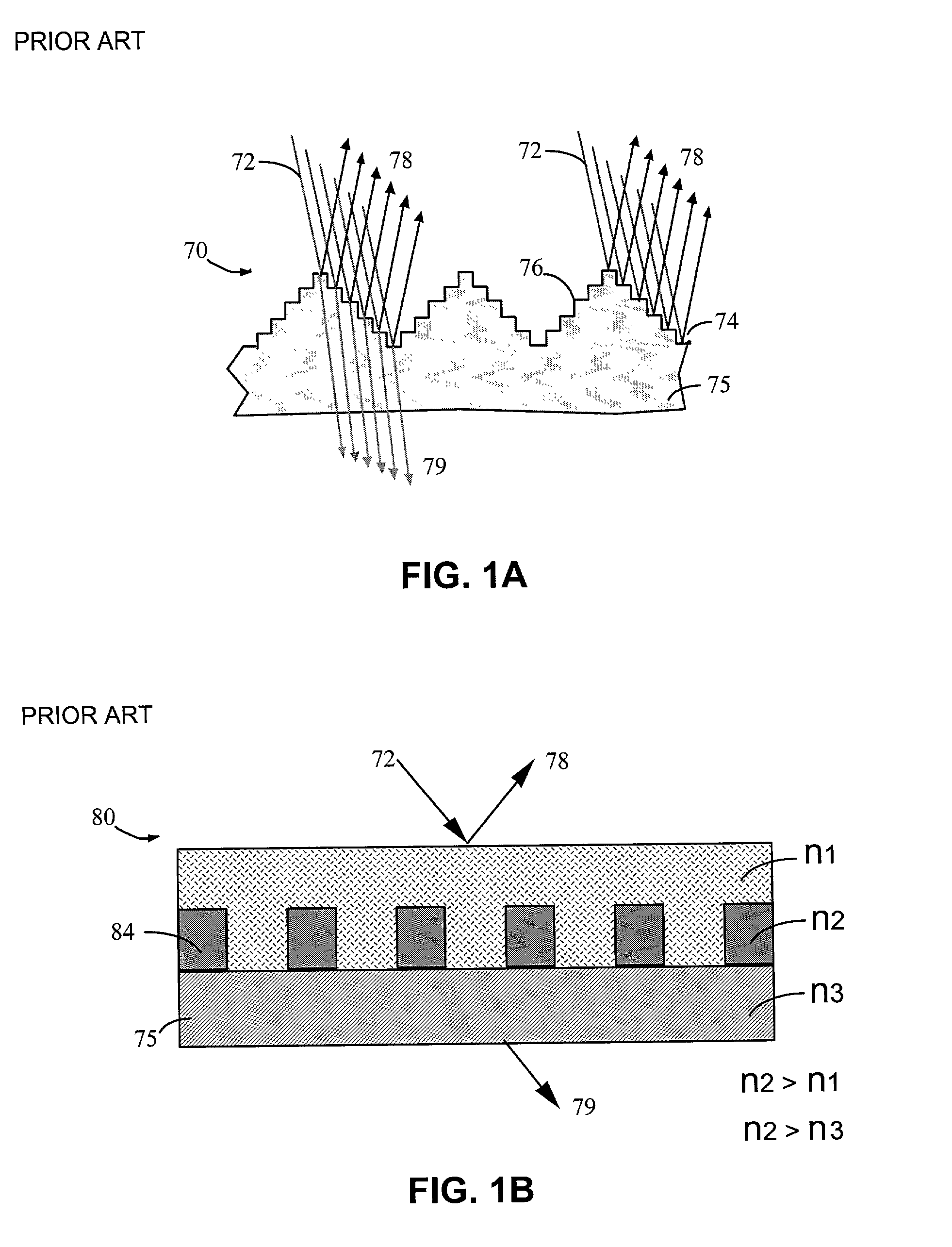
[0036] Prior art surface structure filters suitable for use as chemical sensors operate on free space optical beams, and their function can be described by a combination of prevailing theories as depicted in FIGS. 1A-1B. In FIG. 1A an Aztec Surface Structure Resonance 70 is shown where an incident optical beam containing a broad range of wavelengths 72, is partially reflected 74 from phase transitions or steps 76 comprising a structure on the surface of a substrate 75, each reflection adding coherently for only a narrow range of light wavelengths in a reflected beam 78, and having no affect on other wavelengths passed in a transmitted beam 79; in FIG. 1B a guided mode surface structure resonance device 80 is shown where a filtered reflected beam 78 is created only for a light wavelength matching the transverse variation of density 84 imposed by the surface structure shape and composition.

[0037] As shown in the pr...


PUM

PropertyMeasurementUnit
wavelengthsaaaaaaaaaa
heightaaaaaaaaaa

Abstract

An apparatus for filtering electromagnetic waves, the apparatus comprising a substrate having a surface relief structure containing at least one dielectric body with physical dimensions smaller than the wavelength of the filtered electromagnetic waves, such structures repeated in a two dimensional array covering at least a portion of the surface of the first substrate. Also disclosed is a material sensor utilizing this apparatus.

Description

CROSS-REFERENCE TO RELATED APPLICATIONS[0001] This application claims priority of Application No. 60 / 244,312 filed on Oct. 30, 2000 entitled "Resonant Reflection Microarray", Application No. 60 / 283,314 filed on Apr. 12, 2001 also entitled "Resonant Reflection Microarray", and Application No. 60 / 310,399 filed on Aug. 6, 2001 entitled "Optical Device For Filtering And Sensing", the teachings of which are incorporated herein by reference.FIELD OF THE INVENTION[0002] This invention is in the field of biological or chemical sensors useful for detecting and identifying chemicals such as pollutants, or biological matter such as DNA or proteins. High speed detection is achieved directly without the use of intermediate chemical labels such as fluorescent materials.BACKGROUND OF THE INVENTION[0003] Optical sensor systems that can identify and detect the concentration of various materials in a sample, have a great number of applications in the fields of biotechnology and chemical analysis. Hig...

Claims


Application Information

Patent Timeline
Patent Type & Authority Applications(United States)
IPC IPC(8): G02B5/18G02B5/20
CPCG02B5/204G02B1/005
Inventor HOBBS, DOUGLAS S.COWAN, JAMES J.
Owner X BODY
Why Eureka
Try Eureka