Constant velocity drive rotary-wing aircraft rotor with torque splitting differential

a constant velocity drive and rotor technology, applied in the direction of propellers, propulsive elements, water-acting propulsive elements, etc., can solve the problems of reducing the overall performance of the helicopter, accelerating and decelerating blades, and affecting the life of the rotor components

Inactive Publication Date: 2003-12-04
EUROCOPTER
View PDF12 Cites 22 Cited by
  • Summary
  • Abstract
  • Description
  • Claims
  • Application Information

AI Technical Summary

Problems solved by technology

On rotary-wing aircraft rotors, it is known that, since the introduction of the flapping hinge on autogyro and helicopter rotors, tilting the rotor where coning is present, whether this tilting is desired and generated by controlling the cyclic pitch or the unwanted result of the asymmetry between an advancing blade and a retreating blade, causes stresses in the drive plane of the blades which tend to cause the blades to accelerate and decelerate in the course of a revolution of the rotor.
This acceleration and deceleration of the blades over a revolution of rotation has a disastrous effect on the lives of the rotor components, due to the fact that these variations in speed generate stresses which are all the more substantial as the rigidity of the rotor components is high.
These improvements to the original rotary-wing aircraft rotor concepts have led to a rotor fully articulated in pitch, flapping and drag, the main disadvantage of which was to be subject to instability of the ground resonance or air resonance type, which made it necessary to develop and use drag dampers, also known as frequency adapters, or again elastic return drag struts with built-in damping.
In both cases, the presence of the drag dampers increases the aerodynamic drag of the rotor, in particular at the hub and where the hub is connected to the blades, which reduc...

Method used


Image

  • Constant velocity drive rotary-wing aircraft rotor with torque splitting differential
  • Constant velocity drive rotary-wing aircraft rotor with torque splitting differential
  • Constant velocity drive rotary-wing aircraft rotor with torque splitting differential

Examples


Embodiment Construction

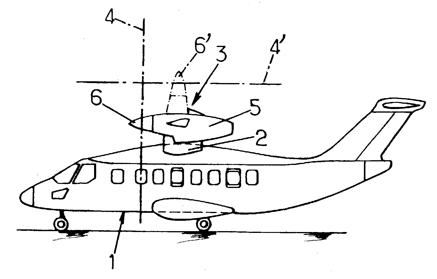
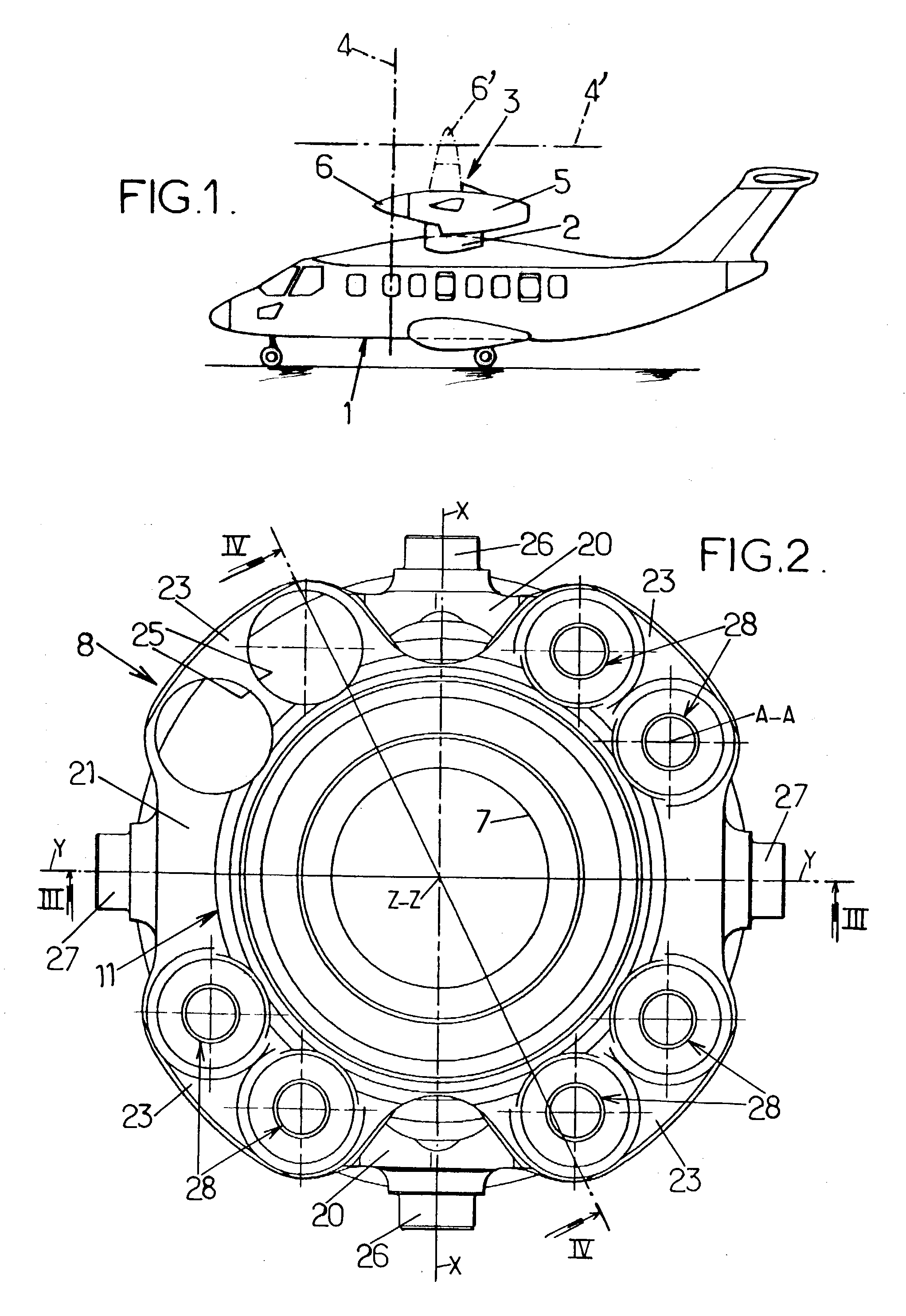
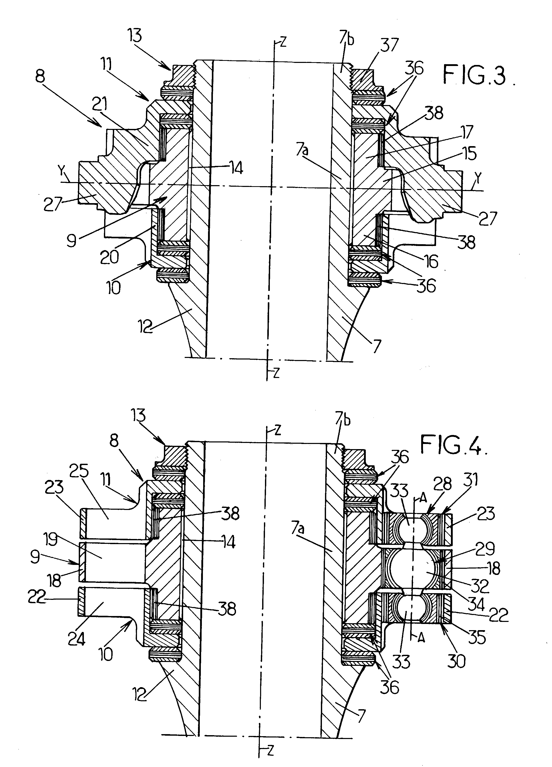
[0060] FIGS. 2 to 6 show a differential torque splitting mechanism, fitted to a rotor mast, for driving in rotation the hub of a convertible aircraft tilting rotor, as described above with reference to FIG. 1.

[0061] In a first embodiment, this differential mechanism may be associated with a two-gimbal device, as shown in FIGS. 7 and 8, for driving in rotation and tilting a rotor hub, which may be such as shown in FIGS. 9 and 10, on which, according to a second embodiment, the differential mechanism drives the hub in rotation via drive links, the tilting means comprising half of a flapping thrust bearing as shown in FIG. 10.

[0062] In FIGS. 2 to 6, the mast 7 of the rotor, driven by its base (not shown) in rotation about its longitudinal axis Z-Z, supports, at its free end portion (at the opposite end to the base) a differential mechanism, designated as a whole by the number 8. This mechanism 8, which belongs to the means for constant velocity drive of the rotor hub, mainly comprises ...


PUM


Abstract

A constant velocity drive mechanism of a rotary-wing aircraft rotor, comprises a torque splitting differential mechanism, comprising a driving disc integral in rotation with a rotor mast and connected to each of two driven discs either side of the driving disc, by a least one connecting pin hinged to each of the discs by one of three ball joint connections. Each of the driven discs is connected to a hub of the rotor by at least one of two driving devices, each of which is also hinged to the hub, so as to drive the hub in rotation about a geometrical axis which can be inclined in all directions about the axis of rotation of the mast.

Description

[0001] The invention relates to a rotary-wing aircraft rotor with constant velocity drive, in particular for a convertible aircraft supporting two generally fixed wings and at least one tilting rotor.[0002] Although the constant velocity drive rotor of the invention can be used as a helicopter rotor, in particular as a tail or anti-torque rotor, a particularly advantageous application of such a constant velocity drive rotor consists in fitting it to convertible aircraft with tilting rotors, particularly of the type known and described in FR 2 791 319, FR 2 791 634 and FR 2 798 359, to which reference may advantageously be made for further details.[0003] Briefly, such a convertible aircraft with tilting rotors generally comprises, as shown schematically in FIG. 1, a fuselage 1, of the aircraft fuselage type, supporting two fixed wings 2, for example high wings, raised with respect to the fuselage 1, each wing 2 itself supporting a power pod 3, housing a power unit driving in rotation...

Claims


Application Information

Patent Timeline
IPC IPC(8): B64C27/28B64C29/00F16D3/70
CPCB64C29/0033B64C27/41B64C27/32F16D3/70
Inventor ZOPPITELLI, ELIOCORNILLE, ERIC
Owner EUROCOPTER
Why Eureka
Try Eureka