Optical compensatory sheet, liquid-crystal display and elliptical polarizing plate employing same

a technology of optical compensatory sheet and liquid crystal display, which is applied in the direction of polarizing elements, thin material processing, instruments, etc., can solve the problems of insufficient widening of viewing angle, insufficient ensuring of tilt angle of discotic liquid crystal molecules, and finding optical leakag

Inactive Publication Date: 2003-12-04
FUJIFILM CORP
View PDF1 Cites 19 Cited by
  • Summary
  • Abstract
  • Description
  • Claims
  • Application Information

AI Technical Summary

Problems solved by technology

However, when the present inventors actually employed these optical compensatory sheets, optical leaks were found in the direction of incline of the polarizing plate, and it was determined that the viewing angle had not been adequately broadened (to the degree that would be theoretically anticipated).
One reason for the inadequate optical compensation function is that the tilt angle of the discotic liquid crystal molecules cannot be adequately ensured.
However, the use of discotic liquid-crystal molecules of inherently high birefringence creates a problem in that the angle of incline of the discotic liquid-crystal molecules is clearly inadequate.
However, when a polymerizable group is directly bonded to the disk-shaped core, it tends to be difficult to maintain alignment during the polymerization reaction.
If the increase of the air interface polarity is smaller than the above described range, the difference in the polarity between the surface of the alignment layer and the air interface is so small that a sufficient increase in the tilt angle of the discotic liquid crystal compound cannot be obtained.

Method used


Image

  • Optical compensatory sheet, liquid-crystal display and elliptical polarizing plate employing same
  • Optical compensatory sheet, liquid-crystal display and elliptical polarizing plate employing same
  • Optical compensatory sheet, liquid-crystal display and elliptical polarizing plate employing same

Examples


example 1

[0121] (Measurement of an Air Interface Polarity of an Optically Anisotropic Layer)

[0122] 2 g of a polymer shown bellow was dissolved in mixed solvent of 36 g of pure water and 12 g of methyl alcohol, and the solution was applied to a transparent glass substrate. After drying at 100.degree. C. for 2 minutes to form a layer, an alignment layer was formed by rubbing treatment of the layer with tucked in by 0.2 .mu.m. The thickness of the alignment layer was 0.5 .mu.m.

[0123] Polymer for production of an alignment layer 25

[0124] The polymerization degree of the polymer was 300 and the molar ration x:y:z was 1.7:86.3:12.

[0125] The alignment layer was cut into the dimension of 2 cm.times.2.5 cm and the coating liquid containing following components was applied to the alignment layer by spin coating method with 2000 rpm. An optically anisotropic layer having a thickness of 1.5 .mu.m was formed on the alignment layer.

1 Coating liquid of optically anisotropic layer Discotic liquid-crystal co...

examples 2 to 5 , 1

Examples 2 to 5, 1' and 2'

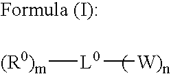
[0128] Various optically anisotropic layers were formed in the same manner as the example 1, except that various compounds represented by the formula (I) shown in Table 1 were respectively used with the same mixed ration and the amount in place of Compound No. 19. The air interface polarities of the formed optically anisotropic layers were measured in the same manner as the example 1. The results are shown in Table 1.

2 TABLE 1 Air Contact Angle interface (deg) Surface Free Energy Example control methylene (mN / m) Polarity No. agent water iodide .gamma.s.sup.d .gamma.s.sup.p .gamma. .gamma.s.sup.p / .gamma.s.sup.d P.sub.add / P.sub.non-add* 1 No.I-19 29.5 21.2 31.6 16.4 48.0 0.52 1.57 2 No.I-20 25.8 30.8 11.1 43.0 54.1 3.87 11.70 3 No.I-21 28.7 33.3 17.8 25.8 43.7 1.44 4.36 4 No.I-23 21.3 36.0 13.6 41.5 55.1 3.05 9.24 5 No.I-81 24.7 34.2 16.0 33.6 49.6 2.10 6.36 .sup. 1' Compound(A) 30.5 15.0 38.0 12.5 50.5 0.33 1.00 .sup. 2' non 30.5 15.0 38.0 12.5 50.5 0.33 --*...

example 6

[0131] (Preparation of the Transparent Support)

[0132] The following components were charged to a mixing tank and stirred with heating to prepare a cellulose acetate solution (dope).

3 Composition of cellulose acetate solution composition Cellulose acetate with a 60.9 percent 100 weight parts degree of acetation Triphenyl phosphate 6.5 weight parts Biphenyldiphenyl phosphate 5.2 weight parts Retardation enhancer (1) described below 0.1 weight part Retardation enhancer (2) described below 0.2 weight part Methylene chloride 310.25 weight parts Methanol 54.75 weight parts 1-Butanol 10.95 weight parts Retardation enhancer (1) 30 Retardation enhancer (2) 31

[0133] The dope obtained was made to flow out of a nozzle onto a drum cooled to 0.degree. C. It was peeled off while having a solvent content of 70 weight percent, the two edges of the film in the transverse direction were fixed with a pin tenter, and in the area where the solvent content was from 3 to 5 weight percent, the film was drie...


PUM

PropertyMeasurementUnit
mean tilt angleaaaaaaaaaa
RHaaaaaaaaaa
temperatureaaaaaaaaaa

Abstract

A novel optical compensatory sheet is disclosed the sheet comprises a transparent support and an optically anisotropic layer formed of discotic liquid-crystal molecules thereon. The anisotropic layer comprises at least one air interface control agent, thereby having an air interface polarity of at least 1.5-fold relative to that of a layer which does not comprise said air interface control agent. An optical compensatory sheet comprising a transparent support and an optically anisotropic layer formed of discotic liquid-crystal molecules thereon, wherein said anisotropic layer comprises at least one compound denoted by formula (I) is also disclosed.

Description

[0001] The present invention relates to the optical compensatory sheets employed in elliptical polarizing plates and liquid-crystal displays, and to elliptical polarizing plates and liquid-crystal displays employing the same.DESCRIPTION OF RELATED ART[0002] Liquid-crystal displays are comprised of a liquid-crystal cell, polarizing elements, and optical compensatory sheets (phase differential sheets). In transmitting liquid-crystal displays, two plates of polarizing elements are mounted on either side of a liquid-crystal cell, and one or two optical compensatory sheets are positioned between the liquid-crystal cell and the polarizing elements. In reflecting liquid-crystal displays, a reflective plate, a liquid-crystal cell, an optical compensatory sheet, and a polarizing element sheet are sequentially positioned. The liquid-crystal cells are comprised of rod-shaped liquid-crystal elements, two substrates for sealing these elements, and two electrode layers for applying a voltage to t...

Claims


Application Information

Patent Timeline
Patent Type & Authority Applications(United States)
IPC IPC(8): G02B5/30G02F1/13363
CPCG02B5/3016G02F2413/10Y10T428/1041Y10T428/1036Y10T428/10C09K2323/00C09K2323/03C09K2323/031
Inventor MORISHIMA, SHINICHIKAWATA, KENYANAGI, TERUKAZU
Owner FUJIFILM CORP
Why Eureka
Try Eureka