Device for integrating demultiplexing and optical channel monitoring

a demultiplexing and optical channel technology, applied in the field of photonics, can solve the problems of large devices that are difficult to manufacture, have potential pdl problems, and often exhibit polarization dependent loss of optical taps

Active Publication Date: 2004-01-15
ENABLENCE +1
View PDF9 Cites 8 Cited by
  • Summary
  • Abstract
  • Description
  • Claims
  • Application Information

AI Technical Summary

Problems solved by technology

One major difficulty with this approach is that in integrated optics, optical taps often exhibit a polarization dependent loss (PDL), a major problem for all telecommunications components.
Also, it is difficult to manufacture even a single optical demultiplexer on a single chip.
Integrating three building blocks into a common device results in a large device that is difficult to manufacture and has potential PDL problems.

Method used


Image

  • Device for integrating demultiplexing and optical channel monitoring
  • Device for integrating demultiplexing and optical channel monitoring
  • Device for integrating demultiplexing and optical channel monitoring

Examples


example no.2

EXAMPLE NO. 2

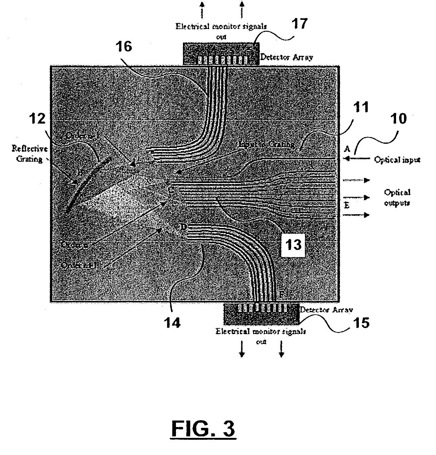
[0026] In the embodiment shown in FIG. 3 an optical signal 10 consisting of many different wavelength channels is input to the input waveguide 11 at A. The device operation is identical to that described in Example No. 1, with the main optical signal being demultiplexed and output through order n. However, in this example there are also monitor output waveguides 16 positioned to collect light of order n+1, as well as n-1. The monitor output waveguides 14 for order n+1 can be identical to those described in Example No. 1, positioned on-grid at channel center, and provide information on the power in each channel. The monitor outputs for order n-1, however, can be positioned off-grid, e.g. between channels, and provide information on the inter-channel noise.

[0027] The outputs can also be designed so that the ratio between complementary detectors is a known function of wavelength, which allows the device to monitor the wavelength of each channel. This can be accomplished, f...


PUM


Abstract

A method for integrating power monitoring capabilities with passive demultiplexing operations, utilizing the high-order diffraction from an optical diffraction grating. The technique helps avoid insertion loss and polarization dependent loss penalties, and device size penalties, typically incurred with optical taps and multiple diffraction gratings. The technique can also be modified slightly to provide information on channel wavelength and optical signal-to-noise-ratio, as well as channel power.

Description

[0001] This application claims the benefit under 35 USC 119(e) of prior U.S. provisional application serial No. 60 / 386,717 filed Jun. 10, 2002.[0002] 1. Field of the Invention[0003] This invention relates to the field of photonics, and in particular to a device for integrating demultiplexing and optical channel monitoring. The invention is applicable to integrated optical components, as well as components based on bulk-optics.[0004] 2. Description of Related Art[0005] In an optical telecommunications network based on dense wavelength division multiplexing (DWDM), several closely-spaced wavelength channels are multiplexed onto a single optical fiber and transmitted to another system node where the channels are demultiplexed and detected individually. It is very important in DWDM networks to monitor the power in each wavelength channel, as well as other channel information, such as wavelength and optical signal to noise ratio (OSNR), which can vary significantly from channel to channe...

Claims


Application Information

Patent Timeline
Patent Type & Authority Applications(United States)
IPC IPC(8): G02B6/00G02B6/12G02B6/34
CPCG02B6/0001G02B6/29385G02B6/12007G02B6/12004
Inventor PEARSON, MATTKRUG, PETER
Owner ENABLENCE
Why Eureka
Try Eureka