
Wiper blade for cleaning glass panes, especially of motor vehicles, and method for the production of said wiper blade

a technology for cleaning glass and wiper blades, which is applied in the direction of vehicle maintenance, vehicle cleaning, domestic applications, etc., can solve the problems of drive unit, run counter, and poor window cleaning quality

Inactive Publication Date: 2004-02-12
ROBERT BOSCH GMBH
View PDF8 Cites 70 Cited by
  • Summary
  • Abstract
  • Description
  • Claims
  • Application Information

AI Technical Summary

Benefits of technology

[0005] In the wiper blade of the invention, having the definitive characteristics of claim 1, a wiper blade is obtained whose support element, because of its relatively low carbon content can be welded well. In the region of the weld connection, there is no brittleness, thus avoiding the adverse effects of brittleness there. The only slight proportions of phosphorus and sulfur contribute further in this respect. A wiper blade with a support element of this kind is especially well suited to wiping windows that have a moderate spherical curvature.[0006] If in a refinement of the invention the quenched and tempered steel used for the support element also has a proportion of chromium of 0.30% to 0.60% and moreover has a proportion of boron of at least 0.008%, a wiper blade is obtained whose support element has only very slight relaxation in its yielding direction and moreover has improved properties in terms of hardenability, weldability, and reformabilty.[0007] Further improvement in terms of the demands made of the support element of the wiper lip is attained if the quenched and tempered steel for producing the support element has the following alloy components: carbon, 0.24% to 0.36%; silicon, 0.40%; manganese, 1.10% to 1.50%; phosphorus, 0.035%; sulfur, 0.035% to 0.40%; chromium, 0.30% to 0.60%, and boron, at least 0.008%. In such a support element, nor only are the aforementioned properties in terms of dimensional stability, hardenability, weldability, and great durability of the shaping curvature improved, but the problematic weld connection zone can be embodied in a problem-free way, and good paintability is achieved.[0008] In another refinement of the invention, following further alloy components are added to the quenched and tempered steel for producing the support element: aluminum, 0.04% and niobium, 0.03%. These alloy ingredients likewise improve the hardenability, weldability, and reformabilty of the wiper blade support element.[0009] It proves especially favorable if, in an alternative proposal, the quenched and tempered steel for producing the support element has the following alloy components: carbon, 0.18%; silicon, 0.50%; manganese, 1.80%; phosphorus, 0.015%; sulfur, 0.002%; aluminum, 0.04% and niobium, 0.03%. In this kind of quenched and tempered steel as well, the aforementioned deficiencies in the region of the problematic welding zone no longer arise. The hardenability and reformability are improved decisively in this case, as is the durability of the shaping,[0010] In a method for producing a bandlike-elongated support element made from a spring-elastic quenched and tempered steel and belonging to a wiper blade, it has proved especially advantageous if as the starting material for the support element, a wire of round cross section is used, which is shaped without waste into a band by cold rolling on two opposed sides. In this method, the microstructure of the material resulting from the drawing of the wire is not interrupted but only reformed, which is advantageous particularly for the shaping curvature of the support element.[0011] Other advantageous refinements and features of the invention are disclosed in the ensuing description of exemplary embodiments shown in the associated drawing.

Problems solved by technology

If this force exceeds a certain magnitude, however, the drive unit--that is, the electric motor and a gear downstream of it--is overloaded, while if the contact pressure is slight, the quality of window cleaning suffers.
The bores required in the support element for this purpose affect its spring properties in a way that can be controlled only with great difficulty, since the microstructure created in the production of the starting material is interrupted at multiple points.
Producing the requisite relatively sharp-edged bending edge for this purpose makes certain demands of the available material for the support element, but these demands run counter to he need for great durability of the spring properties of the support element.
However, in the spring band steels used to produce the spring rails for the known, aforementioned bracket-system wiper blades, this intrinsically single, economical welded connection, which moreover affects the spring properties of the support element only insignificantly, leads to the formation of pores and microscopic cracks from brittleness in the welded region, as well as rehardening zones in the weld seam and the like.
These problems can be only partly eliminated by providing an intermediate thermal treatment, which is expensive.
Besides, in such steels, satisfactory quality in such other steps in the production process for the support element provided with the connection device, such as painting, which is done to avoid the irritating reflection in bare steels, is hardly attainable.
Also in these spring band steels, the requisite dimensional stability for the shaping curvature, which is ascertained specially for every kind of window contour, is not permanently assured; nor is it assured that the required tolerances will be met over the long term.

Method used


Image

  • Wiper blade for cleaning glass panes, especially of motor vehicles, and method for the production of said wiper blade
  • Wiper blade for cleaning glass panes, especially of motor vehicles, and method for the production of said wiper blade
  • Wiper blade for cleaning glass panes, especially of motor vehicles, and method for the production of said wiper blade

Examples


Embodiment Construction

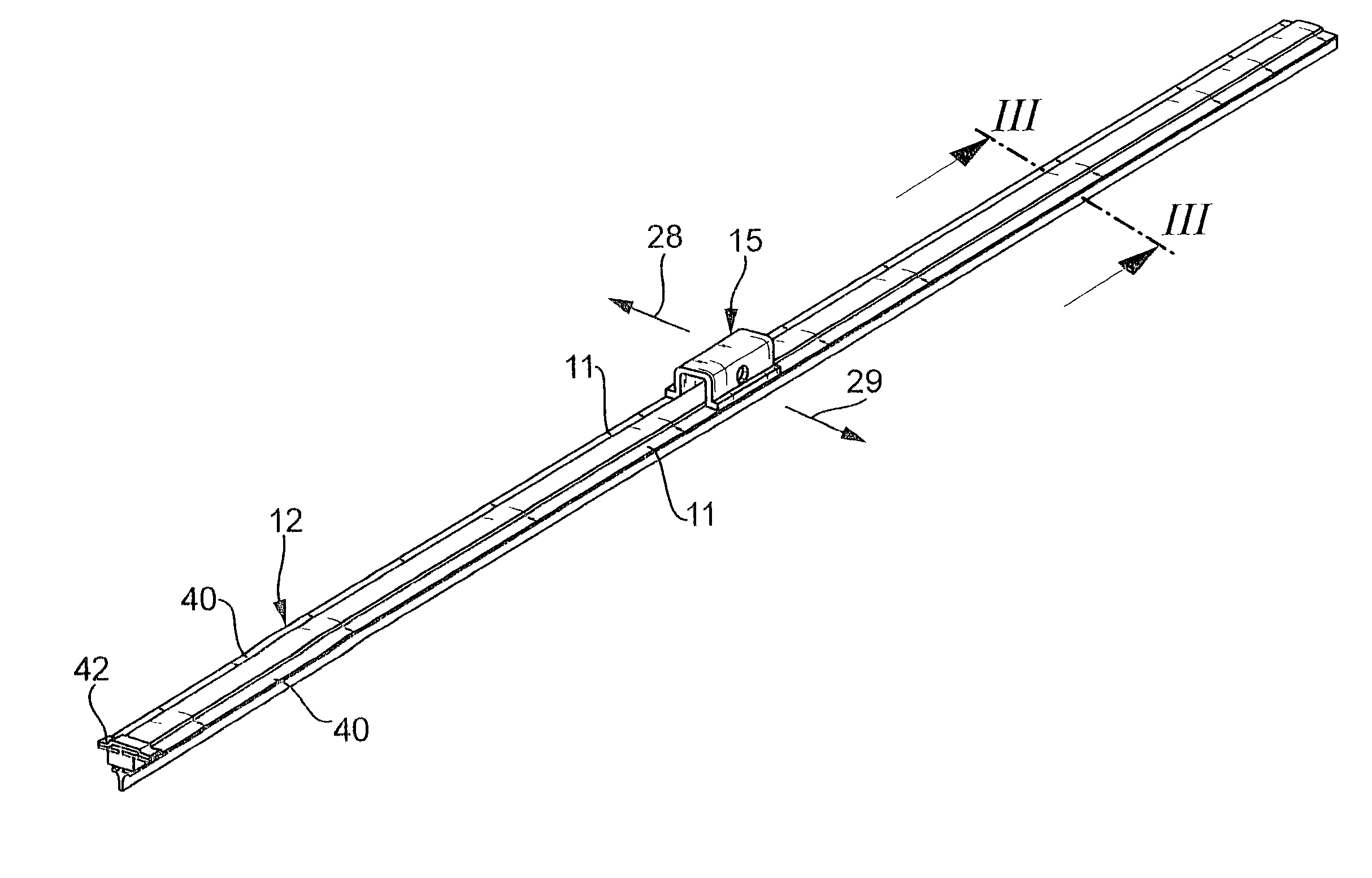
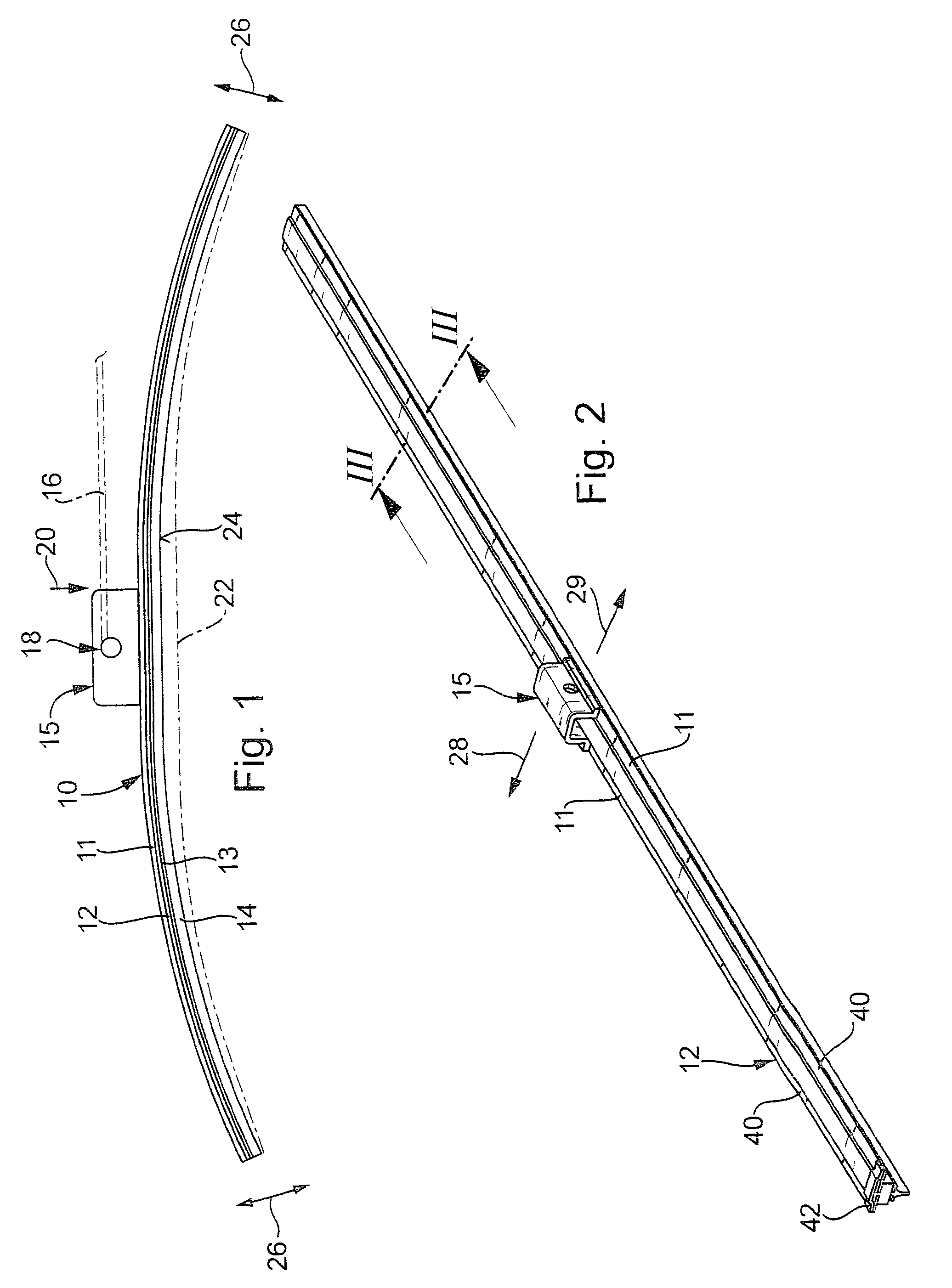
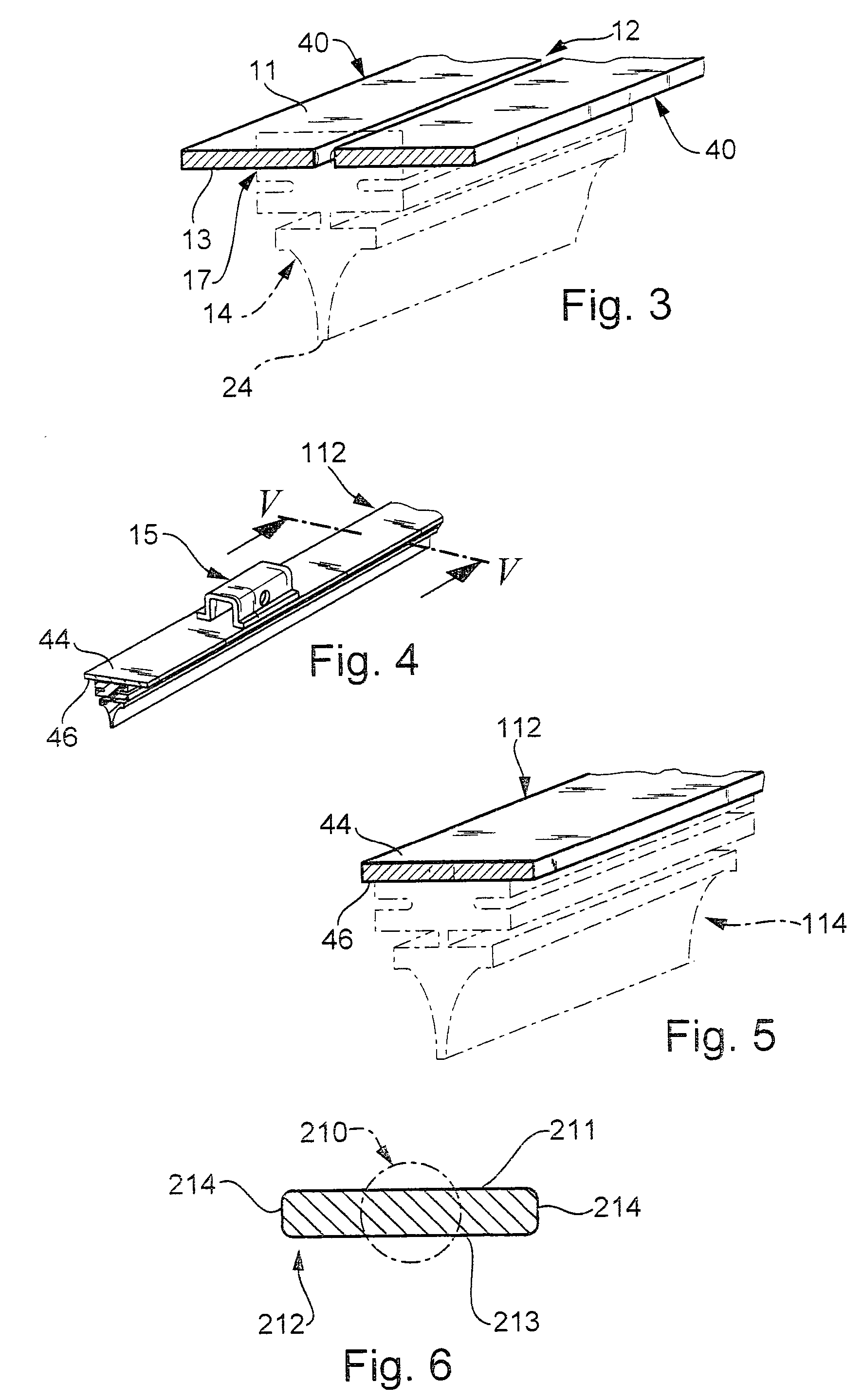
[0013] A wiper blade 10 shown in FIG. 1 has a bandlike-elongated, spring-elastic support element 12 (FIGS. 2 and 3), to whose lower side 13, oriented toward the window, an elongated, rubber-elastic wiper strip 14 is secured parallel to the longitudinal axis. In the middle of the underside of the support element 12, which can also be called a spring rail, is a connection device, with whose aid the wiper blade 10 can be joined separably and pivotably to a driven wiper arm 16, represented by dot-dash lines. To that end, the wiper arm 16 is provided on its free end with the part 18 of the connection device toward the wiper arm, this part not being shown in detail. The wiper blade 16 is urged in the direction of the arrow 20 toward the window to be wiped--such as a motor vehicle windshield--whose surface is suggested in FIG. 1 by a dot-dash line 22. Since the line 22 is meant to represent the most pronounced curvature of the window surface, it is quite clear that the shaping curvature of...


PUM


Abstract

A wiper blade is proposed for cleaning windows, especially of motor vehicles, is proposed, which is provided with an elongated, rubber-elastic wiper strip that can be placed against the window, which wiper strip is disposed on the lower band face (13), oriented toward the window, of a bandlike-elongated support element (12) made from a spring-elastic steel, on whose other, upper band face (11) facing away from the middle, particularly in the middle portion of the support element, a device (15) for connecting the wiper blade to the free end, urged toward the window, of a driven wiper arm (16) guided on the motor vehicle is welded. It has proved particularly advantageous, in view of the demands made of the support element, if the support element is made from an alloyed quenched and tempered steel, which has the following alloy components: carbon (C), 0.18% to 0.36%; silicon (Si), 0.40% to 0.50 %; manganese (Mn), 1.10 % to 1.80%; phosphorus (P), 0.015% to 0.035%; and sulfur (S), 0.035% to 0.04%.

Description

PRIOR ART[0001] In wiper blades of the type defined by the preamble to claim 1, the support element is meant to assure the most uniform possible distribution, over the entire field swept by the wiper blade, of the wiper blade contact pressure, originating in the wiper arm, against the window. By means of a suitable shaping curvature of the unstressed support element--that is, when the wiper blade is not resting on the window (FIG. 1)--the ends of the wiper strip, which in wiper blade operation presses completely against the window, are stressed toward the window by the then-tensed support element, even if the radii of curvature of spherically curved vehicle windows change at every position of the wiper blade. The curvature of the wiper blade must accordingly be somewhat greater than that in the swept field, at the most pronounced measured curvature of the window to be wiped, because during wiper operation, the wiper strip, or its wiper lip resting on the window, must press against t...

Claims


Application Information

Patent Timeline
Patent Type & Authority Applications(United States)
IPC IPC(8): B60S1/38
CPCB60S1/3855B60S2001/382B60S1/3875
Inventor KRICKAU, OTTODE BLOCK, PETER
Owner ROBERT BOSCH GMBH
Learn More