Recoating of optical fiber

a technology of coating and optical fiber, applied in the field of coating of optical fiber, can solve the problems of difficult to remove optical fiber, material is sticky with respect to ultraviolet curable coating material (acrylate), and the splicing of optical fiber becomes more common

Inactive Publication Date: 2004-02-26
ARBOIX ESTEBAN +1
View PDF1 Cites 17 Cited by
  • Summary
  • Abstract
  • Description
  • Claims
  • Application Information

AI Technical Summary

Benefits of technology

0013] It is still a further object of the invention to provide such apparatus and method, which provide for long term use of the mold apparatus without any considerable degradation of the same.

Problems solved by technology

Additionally, it has become increasingly more common to splice optical fibers, which have broken, either accidentally, or during appropriate proof testing.
However, while such grooved split mold apparatus is made of Plexiglas.RTM. or quartz in order to be highly transparent to UV light to allow curing of the recoating material by passing UV radiation through the mold, such materials tend to be sticky with respect to the UV curable coating material (acrylate or epoxy).
Thus it may be difficult to remove the optical fiber subsequent to recoating and the recoating may be damaged while doing so.
Such solution is, however, not optimal since it involves an additional operation step in the recoating process, i.e. the spraying of Teflon.RTM. into the groove.
Such operation is costly, time-consuming and difficult to implement, particularly in a fast and reliable automated recoating apparatus.
Further, the amount of Teflon.RTM. sprayed into the groove has to be precisely controlled to avoid too thick layers of Teflon.RTM. as such layers would strongly absorb UV light and thus unfavorably affect the curing process.
Further, such sprayed Teflon.RTM. may also negatively affect the adhesion of the polymer recoating material to the bare glass fiber.

Method used


Image

  • Recoating of optical fiber
  • Recoating of optical fiber
  • Recoating of optical fiber

Examples


Embodiment Construction

[0048] In the following description, for purposes of explanation and not limitation, specific details are set forth, such as particular techniques and applications in order to provide a thorough understanding of the present invention. However, it will be apparent to one skilled in the art that the present invention may be practiced in other embodiments that depart from these specific details. In other instances, detailed descriptions of well-known methods and apparatuses are omitted so as not to obscure the description of the present invention with unnecessary details.

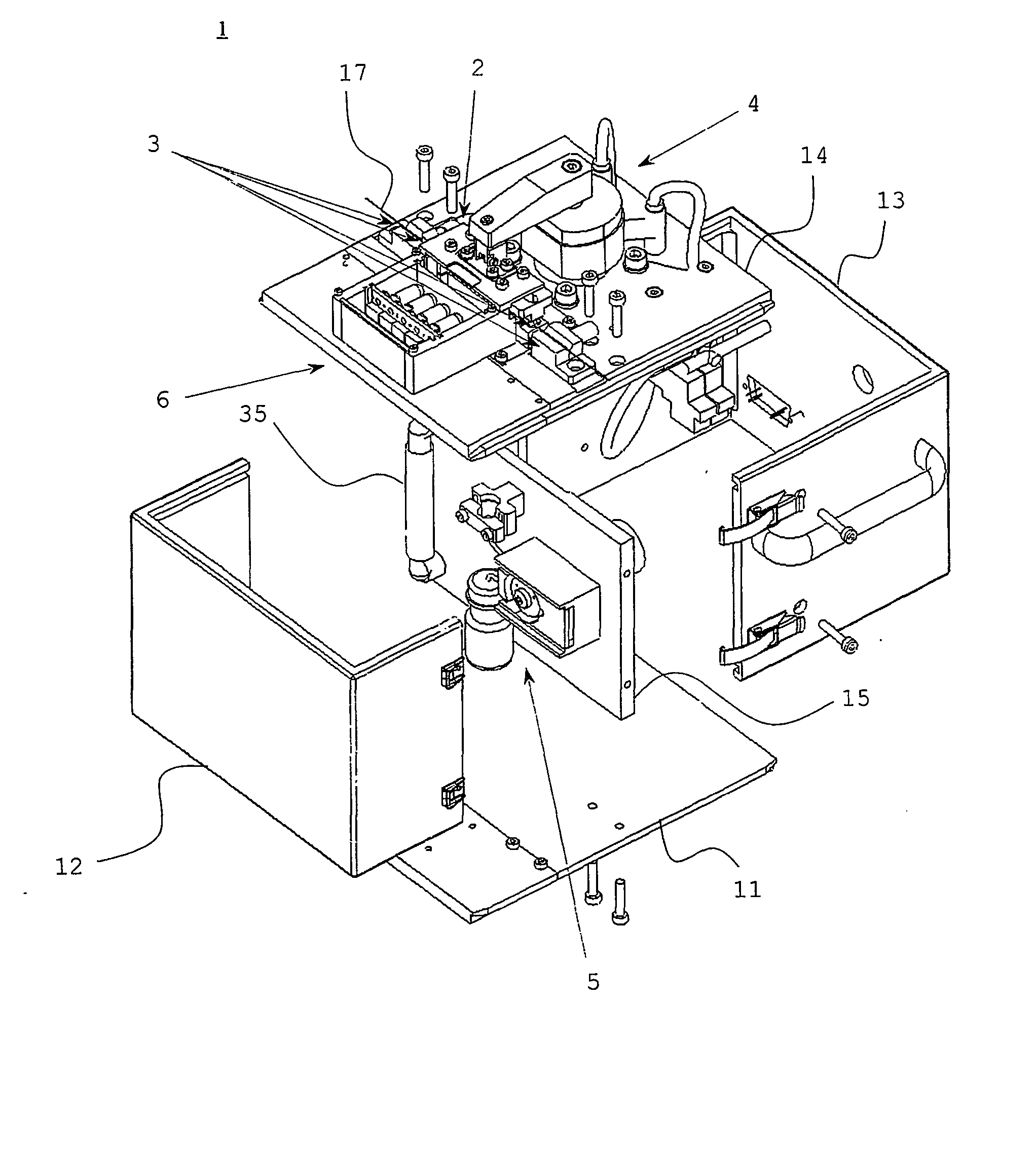
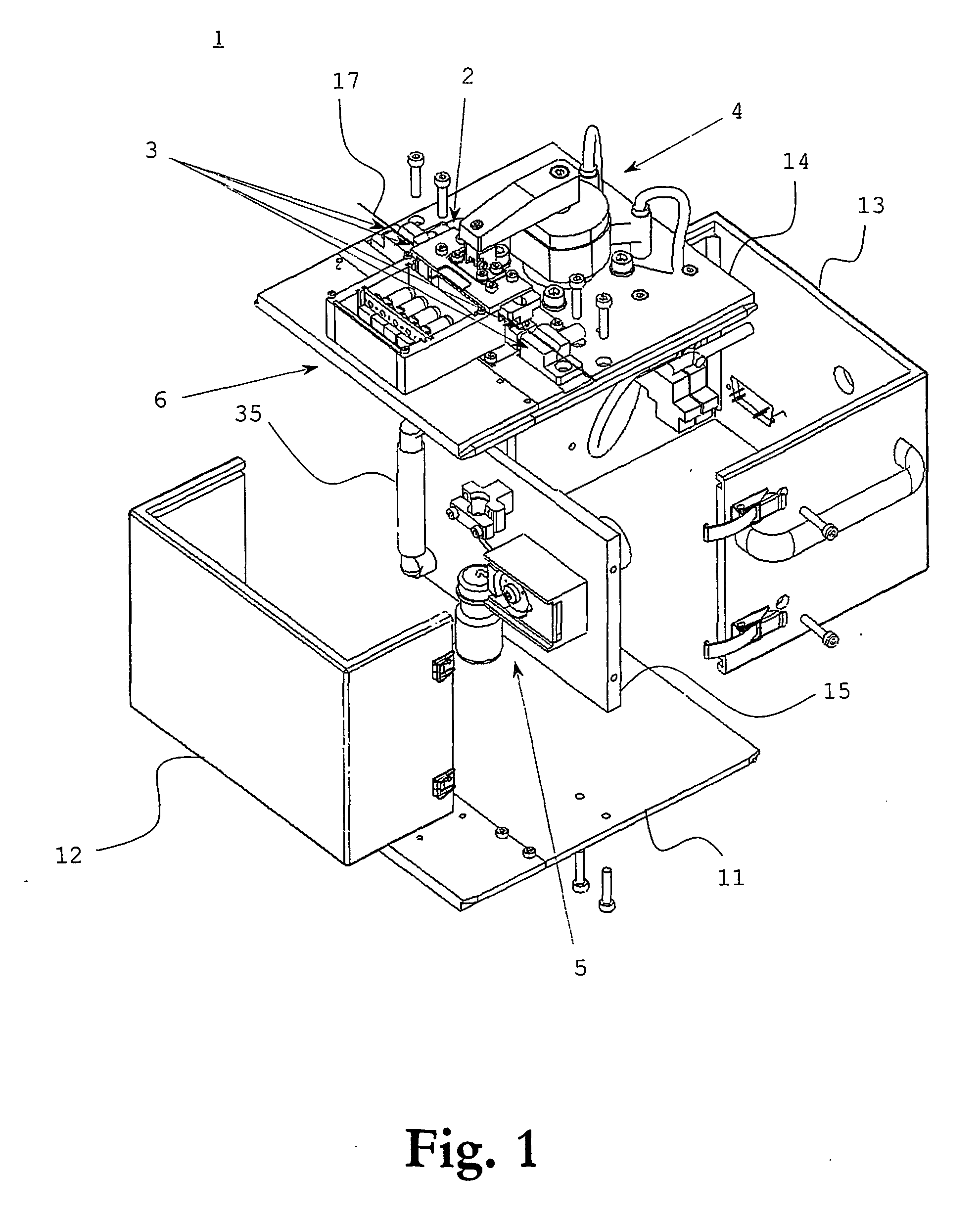
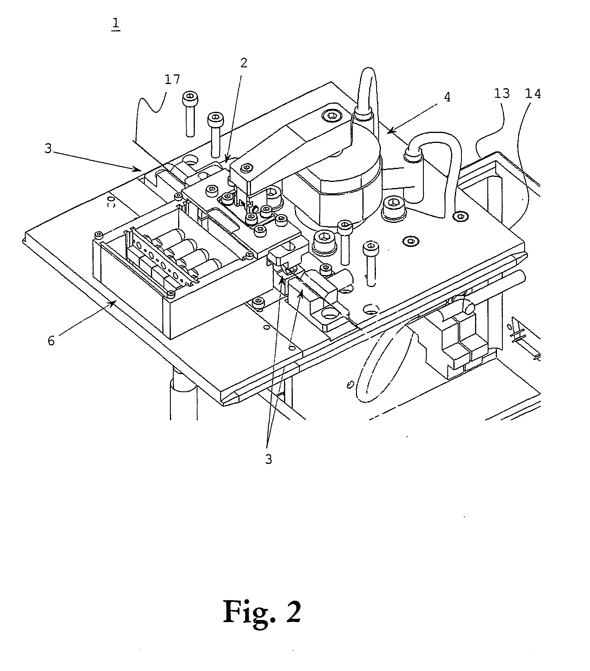
[0049] With reference to FIGS. 1 and 2, which schematically, in exploded perspective views, illustrate a recoating apparatus 1 for recoating spliced end portions of two lengths of optical fibers 17, an embodiment of the present invention will be overviewed. The apparatus comprises five main parts or components: a mold arrangement 2 including a mold cavity, a holding and stretching arrangement 3, a movement and clamping...


PUM

PropertyMeasurementUnit
surface tensionaaaaaaaaaa

Abstract

An apparatus (1) for recoating uncoated and spliced end portions of optical fibers (17) comprises two mold blocks (21a, 22b), each of which includes a groove (22a, 22b), the mold blocks being arrangable in a closed state, wherein the grooves cooperate to form a mold cavity for the fiber end portions, and in an open state, wherein the fiber end portions are insertable into the grooves. The apparatus further includes an injection system (5) for injecting a recoating material into the mold cavity, and a UV curing system (6) for irradiating the recoating material with UV light, thus curing the recoating material. At least one mold block is made of a plastic material comprising a fluoroplastic, e.g. PCTFE, the plastic material being at least partly transparent to UV light to enable the curing system to irradiate the UV curable recoating material with UV light through this mold block.

Description

[0001] The present invention generally relates to fiber optics. More specifically, the invention relates to an apparatus and method for recoating uncoated and spliced end portions of optical fibers.DESCRIPTION OF RELATED ART AND BACKGROUND OF THE INVENTION[0002] The use of optical communications involving the use of optical fibers has increased at an exceptional pace. The main reasons to this are the large transmission capacity of optical fibers; the large distances over which information can be transferred without need of repeaters (around 70 km for optical fiber cables as compared to 2 km for electrical transmission); and the immunity to interferences. Further, the optical fibers are cheap to produce, have low weight, and have small diameters.[0003] Typically, an optical fiber has a diameter on the order of 125 microns, and is covered with a dual protective coating, which increases the outer diameter of the coated fiber to about 250 microns. The coating comprises typically an inne...

Claims


Application Information

Patent Timeline
Patent Type & Authority Applications(United States)
IPC IPC(8): G02B6/255G02B6/38G02B6/44
CPCG02B6/2558
Inventor ARBOIX, ESTEBANDUMITRIU, ION
Owner ARBOIX ESTEBAN
Why Eureka
Try Eureka