Perpendicular magnetic recording medium and magnetic storage apparatus using the same

a magnetic recording medium and perpendicular magnetic technology, applied in the field of magnetic recording mediums, can solve the problems of reducing read output, in-plane recording medium may have a basic performance problem for saving recording information, and difficult to deal with a much higher recording density expected in the futur

Inactive Publication Date: 2004-03-04
HITACHI GLOBAL STORAGE TECH JAPAN LTD +1
View PDF3 Cites 22 Cited by
  • Summary
  • Abstract
  • Description
  • Claims
  • Application Information

AI Technical Summary

Benefits of technology

[0013] A second object of the invention is to provide a magnetic storage apparatus having a recording density of 50 gigabits or more per 1 square inch, by making sufficient use of performance of the above magnetic recording medium.

Problems solved by technology

It is generally considered, however, that it will be difficult to deal with a much higher recording density expected in the future, with the in-plane recording medium, because of a physical limitation.
In other words, the in-plane recording medium may have a problem in basic performance for saving recording information, due to the thermal fluctuation phenomenon of magnetization following the micronization of the very small magnet constituting the recording bit.
As a practical problem, also in the perpendicular magnetic recording medium, there is a problem of a reduction in read output, caused by the thermal fluctuation of magnetization.
Because of small squareness, however, the influence of thermal fluctuation is large, causing a reduction in read output.
Consequently, lattice matching is bad, making it difficult to improve perpendicular orientation as expected.
Even if no heat treatment is necessary for magnetic domain control of the soft magnetic layer, the formation of a Pt non-magnetic intermediate layer by sputtering causes mixing in the interface with the soft magnetic layer depending on energy of sputtering particles, which may generate high coercivity.
The high coercivity of the soft magnetic layer is not preferable, because it increases medium noise.
Thus, diffusion occurs in the interface between Co contained in these layers and the Pt intermediate layer, causing various problems.
Depending on the kind of an element added to the magnetic recording layer, a distance between the nearest neighbor atoms of the magnetic recording layer may become extremely large.
The increase of the grain size in turn causes an increase in medium noise, and thus the crystal grain must be micronized to a certain extent.
Therefore, this point is also different from the conventional art.
%, a conspicuous reduction occurs in a residual magnetic flux density, reducing magnetic flux leaked from the medium, and consequently making it difficult to read a signal by the magnetic head.
However, because of difference in kind between f c. c. and h. c. p. crystal structures, slight disturbance occurs in heteroepitaxial growth in an interface thereof.
In addition, it is not preferable because of difficult production management or the like.
On the other hand, if a layer thickness exceeds 25 nm, a spacing loss between the soft magnetic layer and the magnetic recording layer is increased, and a recording magnetic field becomes steep, making it impossible to narrow the width of a magnetization transition region formed in the medium.
In other words, high-density recording cannot be realized.

Method used


Image

  • Perpendicular magnetic recording medium and magnetic storage apparatus using the same
  • Perpendicular magnetic recording medium and magnetic storage apparatus using the same
  • Perpendicular magnetic recording medium and magnetic storage apparatus using the same

Examples


third embodiment

[0049] Third Embodiment

[0050] In the embodiment, examination was carried out regarding noise reduction by adding an element having a b. c. c. structure to a Cu non-magnetic intermediate layer. FIG. 6 shows a change in medium noise when Cr was added to the Cu non-magnetic intermediate layer by varying concentration in the medium of the structure of the first embodiment. For the measurement of medium noise, a signal was recorded at a recording density 500 kFCI by using the single magnetic pole head, and read back by a GMR head stably floated at a height of 40 nm or lower. In the graph of FIG. 6, the change of medium noise is shown as a change in relative relation to a sample having no Cr added at all set as 1.

[0051] In FIG. 6, in a region where Cr added concentration is set in the range from 0.5 at. % to 30 at. %, a phenomenon of a medium noise reduction is recognized. The setting of Cr concentration equal to 0.5 at. % or lower is not advantageous for micronizing the crystal grain siz...

fourth embodiment

[0053] Fourth Embodiment

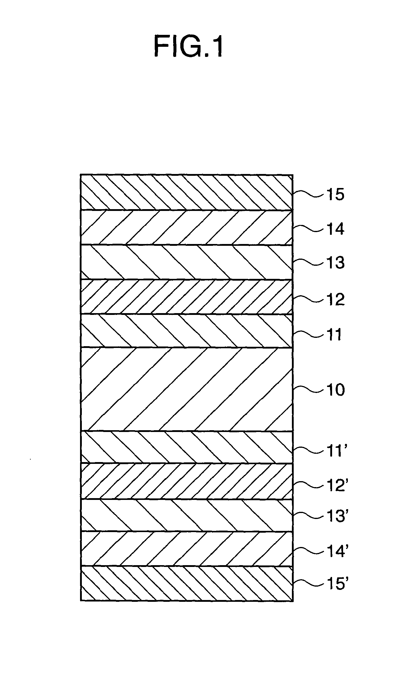
[0054] In the embodiment, examination was carried out as to the layer thickness of the intermediate layer. The structure of a medium examined in the present embodiment will now be described by referring to FIG. 1. On the glass substrate 10 of an outer diameter 65 mm.phi., Fe-8 at. % Ta-12 at. % C soft magnetic layers 11 and 11' are formed by 400 nm. Then, Cu-15 at. % Nb non-magnetic intermediate layers 12 and 12' are formed by changing a layer thickness, and Co-35 at. % Cr non-magnetic intermediate layers 13 and 13' are provided by 0 nm or 10 nm. After forming Co-21 at. % Cr-12 at. % Pt-2 at % Ta magnetic recording layers 14 and 14' by 25 nm, lastly C protective layers 15 and 15' are formed by 5 nm, and lubricant is applied.

[0055] As shown in FIG. 7, in any of the media having CoCr intermediate layers set to 0 nm and 10 nm in thickness, coercivity and squareness were increased with the increase of the layer thickness of the CuNb non-magnetic intermediate laye...

fifth embodiment

[0057] Fifth Embodiment

[0058] FIG. 8(a) is an upper surface view of an example of a magnetic storage apparatus using the perpendicular magnetic recording medium of the invention; and FIG. 8(b) is a sectional view taken on line A-A' of FIG. 8(a). A perpendicular magnetic recording medium 80 is held by a holding tool connected to a magnetic recording medium driver 81, and a magnetic head 82 is disposed oppositely to each surface of the perpendicular magnetic recording medium 80. The recording unit of the magnetic head 82 is composed of a single magnetic pole head, and the reading unit thereof is composed of a magnetoresistive effect device of GMR, TMR or the like. The magnetic head 82 is stably floated low at a height of 40 nm or lower, and driven to a desired track by a magnetic head driver 83 with head positioning accuracy of 0.5 .mu.m or lower.

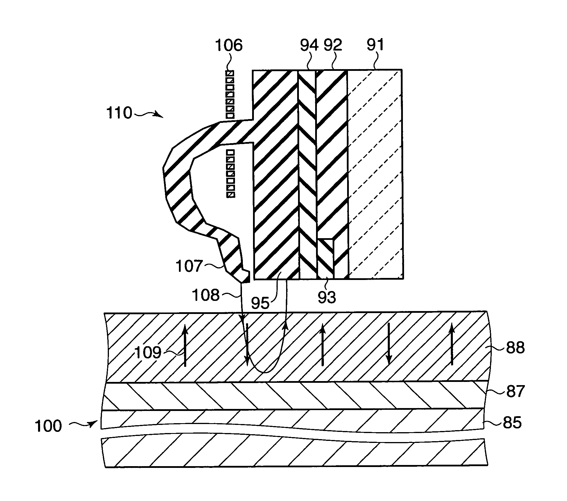
[0059] FIG. 9 is a schematic sectional view showing the situation of magnetic recording in the perpendicular magnetic recording medium by th...


PUM

PropertyMeasurementUnit
thickaaaaaaaaaa
melting pointaaaaaaaaaa
melting pointsaaaaaaaaaa

Abstract

A large-capacity magnetic storage apparatus is disclosed, capable of performing ultra-high density magnetic recording of 50 gigabits or more per 1 square inch. In a perpendicular magnetic recording medium having a non-magnetic intermediate layer and a magnetic recording layer sequentially formed, the non-magnetic intermediate layer is composed of a layer having a face-centered cubic structure and containing a non-magnetic elements excluding Pt. Specifically, the intermediate layer mainly contains at least one selected from the group of elements constituted of Al, Cu, Rh, Pd, Ag, Ir and Au, and is composed of a film having a face-centered cubic (f. c. c.) structure. The magnetic recording layer contains at least Co, Cr and Pt, and is composed of a film having a hexagonal close-packed (h. c. p.) structure. More preferably, a non-magnetic h. c. p. intermediate layer is provided between the non-magnetic intermediate layer and the magnetic recording layer.

Description

BACKGROUND OF THE INVENTION 1. Field of the Invention[0001] The present invention relates to a magnetic recording medium such as magnetic recording drums, magnetic recording tapes, magnetic recording disks, magnetic recording cards, and so on, and a magnetic storage apparatus. More particularly, the invention relates to a perpendicular magnetic recording medium suitable for ultra-high density magnetic recording of 50 gigabits or more per 1 square inch, and a magnetic storage apparatus using the same.[0002] 2. Description of the Related Art[0003] With the popularized use of the Internet in recent years, there have been increases not only in the shipping number of personal computers, but also in the demand for a magnetic recording disk device. Connection to the Internet can be made not only by a personal computer but also by a portable terminal. However, to make the portable terminal itself more convenient, it is essential to incorporate the magnetic recording disk device, and the dem...

Claims


Application Information

Patent Timeline
Patent Type & Authority Applications(United States)
IPC IPC(8): G11B5/64C23C14/06G11B5/65G11B5/66G11B5/667G11B5/73G11B5/738H01F10/26H01F10/30
CPCG11B5/66G11B5/667Y10T428/12465Y10S428/90Y10T428/265G11B5/7325G11B5/7368G11B5/7377G11B5/737G11B5/7373G11B5/676
Inventor YAMAMOTO, TOMOOTAMAI, ICHIROISHIKAWA, AKIRA
Owner HITACHI GLOBAL STORAGE TECH JAPAN LTD
Why Eureka
Try Eureka