Method of removing organic impurities from water

a technology of organic impurities and water, applied in the field of organic impurities removal methods, can solve the problems of complex and expensive hardware required for carrying out high-purity water processing procedures, unable to modify chloroform to yield an ionic entity capable of ion exchange removal, and unable to tolerate such impurities. to achieve the effect of reducing flux rates, reducing temperature, and reducing flux rates

Inactive Publication Date: 2004-03-18
EVOQUA WATER TECH PTE LTD
View PDF7 Cites 52 Cited by
  • Summary
  • Abstract
  • Description
  • Claims
  • Application Information

AI Technical Summary

Benefits of technology

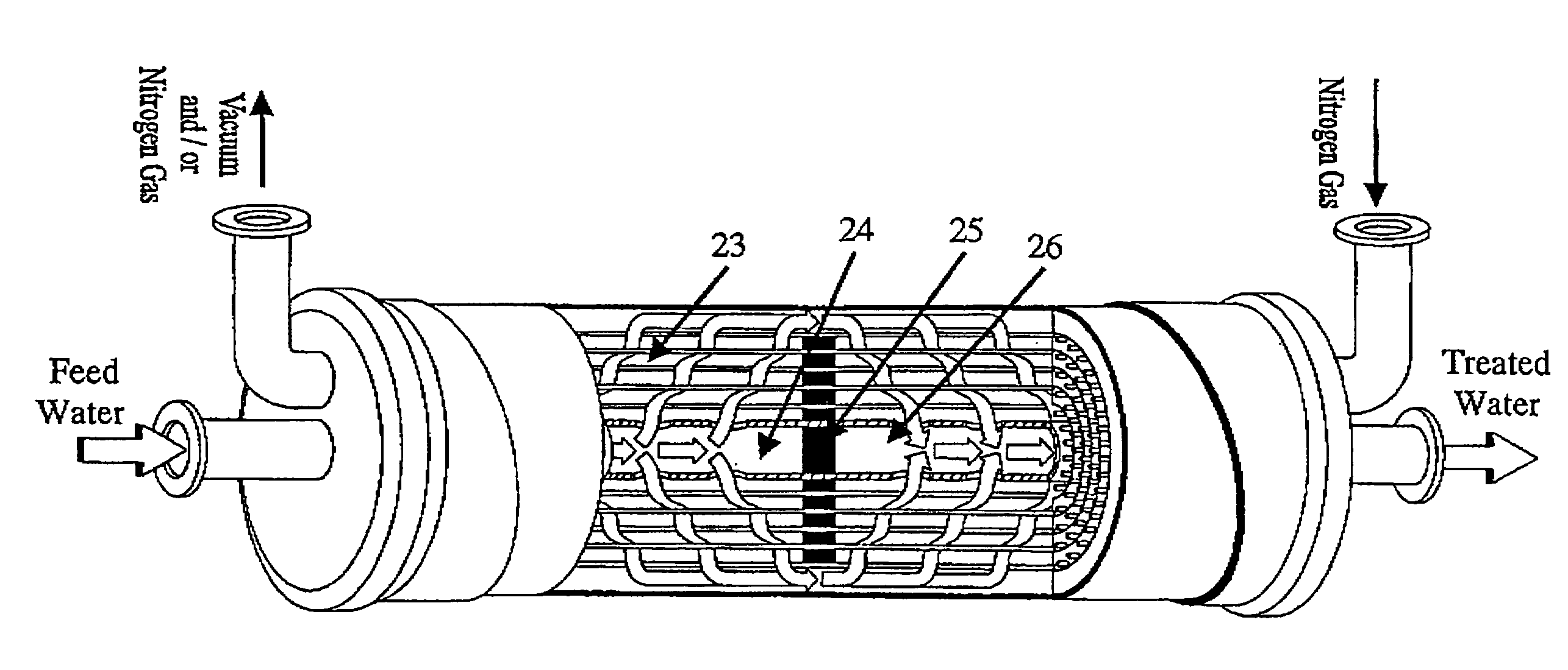
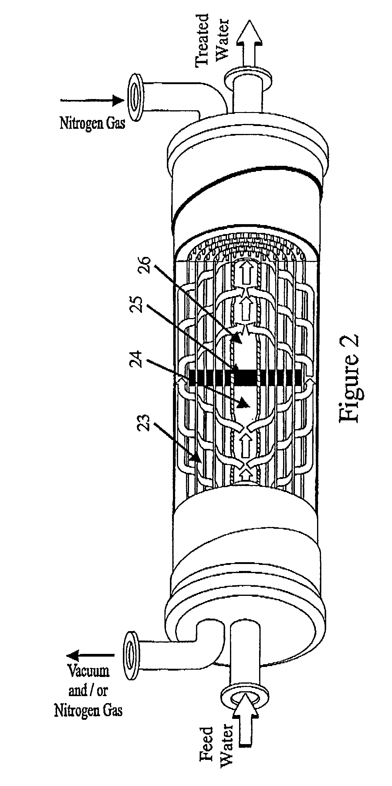
0099] Inlet TOC concentration to the primary membrane degassifier 13 was between 10.0 and 18.0 ppb during the present experimental study. It was found in the present experimental work that the temperature, the applied flux rate and the vacuum level strongly affect the removal of TOC in primary membrane degassifier 13. The improvement in the removal of TOC at lower flux rate and higher temperature and vacuum condition can be attributed to the issues related to the efficiency of mass transfer operation in the primary membrane degassifier 13. It was observed in the present experimental study that the ...

Problems solved by technology

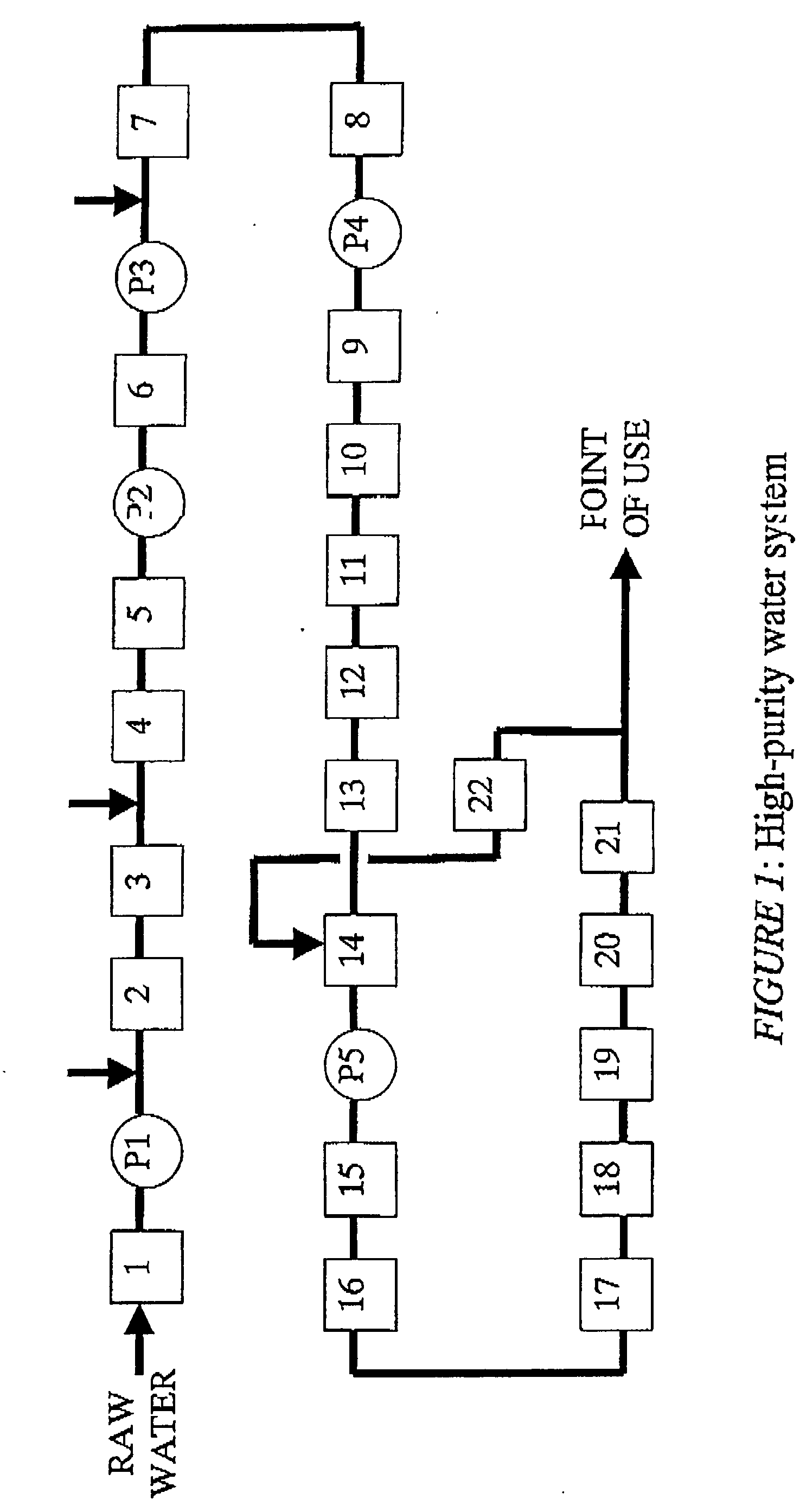
High-purity water processing procedures and the hardware required for carrying them out are complex and expensive.
VOC separation, especially removal at trace level, poses a challenge to the electronic industry where such impurities cannot be tolerated.
UV 185 nm technology, commonly used for the reduction of TOC in high-purity water systems, also cannot m...

Method used


Image

  • Method of removing organic impurities from water
  • Method of removing organic impurities from water
  • Method of removing organic impurities from water

Examples


example 1

[0101] A test was conducted at the pilot test equipment described above according to the invention at a deionised water feed flow rate of 7 gpm. The applied vacuum level was kept constant at -700 mm Hg. The result of analysis for the deionised water so treated is listed in the following Table 4.

4TABLE 4 Performance of two 4-inch contactors in series at 7-gpm flow Temperature, Parameters .degree. C. Feed Water Treated Water % Removal Chloroform, 25.0 16.9 7.5 55.6 ppb 35.0 15.7 6.3 59.9 45.0 14.0 2.5 82.1 TOC, ppb 25.0 11.3 4.9 56.6 35.0 16.8 6.6 60.7 45.0 13.7 2.9 78.8 Dissolved 25.0 2730 2.0 99.93 oxygen, 35.0 3010 0.6 99.98 ppb 45.0 3280 0.4 99.99

example 2

[0102] A test was conducted at the pilot test equipment described above according to the invention at a deionised water feed flow rate of 10 gpm. The applied vacuum level was kept constant at -700 mm Hg. The result of analysis for the deionised water so treated is listed in the following Table 5.

5TABLE 5 Performance of two 4-inch contactors in series at 10-gpm flow Temperature, Parameters .degree. C. Feed Water Treated Water % Removal Chloroform, 25.0 15.2 8.2 46.0 ppb 35.0 14.8 7.4 50.0 45.0 16.6 5.5 66.9 TOC, ppb 25.0 14.3 7.9 44.8 35.0 17.8 9.1 48.9 45.0 11.5 3.9 66.1 Dissolved 25.0 2590 6.1 99.76 oxygen, 35.0 2910 2.0 99.93 ppb 45.0 2740 0.9 99.97

example 3

[0103] A test was conducted at the pilot test equipment described above according to the invention at a deionised water feed flow rate of 14 gpm. The applied vacuum level was kept constant at 650 mm Hg. The result of analysis for the deionised water so treated is listed in the following Table 6.

6TABLE 6 Performance of two 4-inch contactors in series at 14-gpm flow Temperature, Parameters .degree. C. Feed Water Treated Water % Removal Chloroform, 25.0 14.1 10.9 22.7 ppb 35.0 15.4 11.7 24.6 45.0 14.6 9.9 32.2 TOC, ppb 25.0 12.4 9.7 21.8 35.0 16.1 12.4 22.9 45.0 10.2 7.3 28.4 Dissolved 25.0 2810 26.1 99.07 oxygen, 35.0 2620 8.9 99.66 ppb 45.0 3340 6.1 99.82


PUM

PropertyMeasurementUnit
Fractionaaaaaaaaaa
Fractionaaaaaaaaaa
Fractionaaaaaaaaaa

Abstract

In addition to health implications, trihalomethanes (THMs) poses a challenge to the electronic industry where such impurities cannot be tolerated. A process is provided for removing THMs from high-purity water used in the electronic industry. The method of the invention comprises contacting the high-purity water with a membrane degassifier, preferably operating at a temperature exceeding 45° C.

Description

[0001] The present invention relates generally to removal of trihalomethanes (THMs) from high-purity water. More particularly but not exclusively the invention relates to the removal of THMs by an enhanced membrane degassifier operation.[0002] Chlorine is commonly used in water treatment processes for a number of reasons. It acts as a disinfectant, can remove ammonia and other nitrogenous organic compounds, it can also control the taste, smell and colour of the water as well as removing slime or algae. However trihalomethanes (THMs) are produced when chlorine reacts with humic acids, fulvic acids, and other Natural Organic Material (NOM) present in the water.[0003] Trihalomethanes[0004] THMs are the largest class of Disinfection by-products (DBP) present in the most municipal waters. The four common THMs are Chloroform (CHCl.sub.3), dibromochloromethane (CHBr.sub.2Cl), dichlorobromomethane (CHCl.sub.2Br), and bromoform (CHBr.sub.3). Total Trihalomethanes (TTHM) is measured as the su...

Claims


Application Information

Patent Timeline
IPC IPC(8): B01D19/00B01D61/00B01D61/42B01D61/58B01D63/02B01D71/26C02F1/02C02F1/20C02F1/28C02F1/32C02F1/42C02F1/44C02F1/469C02F9/00
CPCB01D19/0031C02F2301/063C02F1/001C02F1/02C02F1/20C02F1/283C02F1/32C02F1/42C02F1/44C02F1/441C02F1/444C02F1/469C02F2101/36C02F2103/04C02F2209/02C02F2209/03C02F2209/05C02F2209/22C02F2209/40B01D61/00B01D19/0073
Inventor DEY, AVIJITTHOMAS, GARETH HUGH
Owner EVOQUA WATER TECH PTE LTD
Why Eureka
Try Eureka