Embolic filter frame having looped support strut elements

Inactive Publication Date: 2004-05-13
WL GORE & ASSOC INC
41 Cites 123 Cited by

AI-Extracted Technical Summary

Problems solved by technology

In therapeutic vascular procedures, liberation of embolic debris (e.g., thrombus, clot, atheromatous plaque, etc.) can obstruct perfusion of the downstream vasculature, resulting in cellular ischemia and/or death.
Additionally, percutaneous transluminal coronary angioplasty (PTCA) with or without adjunctive stent placement, surgical coronary artery bypass grafting, percutaneous renal artery revascularization, and endovascular aortic aneurysm repair have also been associated with complications attributable to atheromatous embolization.
The principle drawback of occlusion balloon techniques stems from the fact that during actuation, distal blood flow is completely inhibited, which can result in ischemic pain, distal stasis/thrombosis, and difficulties with fluoroscopic visualization due to contrast wash-out through the treated vascular segment.
The device also lacks longitudinal compliance.
Thus, inadvertent movement of the catheter results in longitudinal translation of the filter, which can cause damage to the vessel wall and liberate embolic debris.
During positioning within a vessel, the filter material is not fully constrained so that, as the device is positioned through and past a clot, the filter material can potentially snag clot material creating freely floating emboli prior to deployment.
The device also lacks longitudinal compliance.
This device also lacks substantial lo...

Method used

[0104] A further embodiment of the present invention is illustrated in FIGS. 18A through 18C. In this embodiment the filter assembly 30 includes a frame 31 that is slidably mounted to the support wire 36. This attachment may be accomplished through a variety of means, including by providing a collar 46 that is sized slightly larger than the support wire 36 to allow the collar to move relative to the support wire when in use. Stops 114a, 114b are provided on the support wire 36 to ...

Benefits of technology

0013] The present invention is an improved embolic filter frame having looped support struts. The frame configuration of the present invention provides enhanced...

Abstract

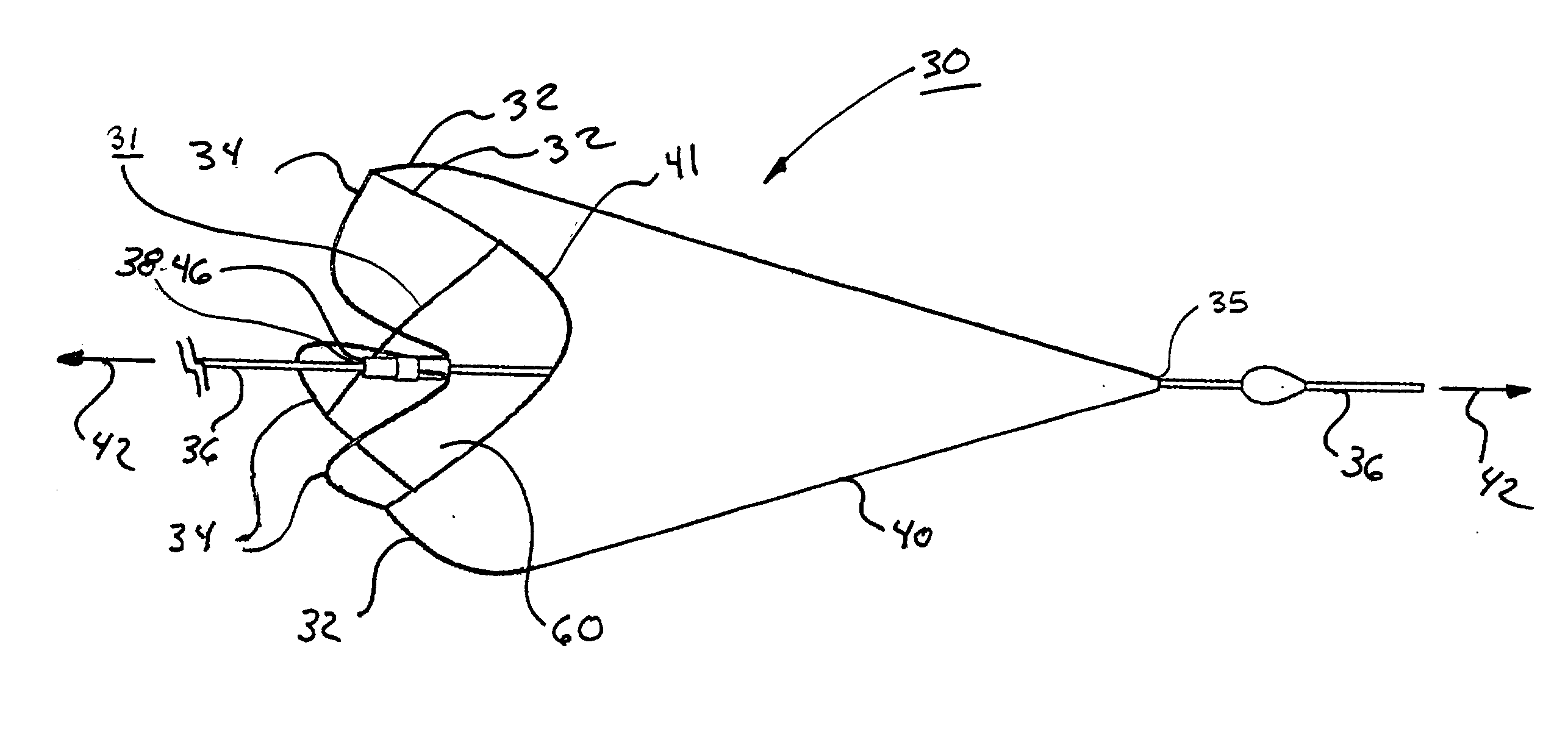
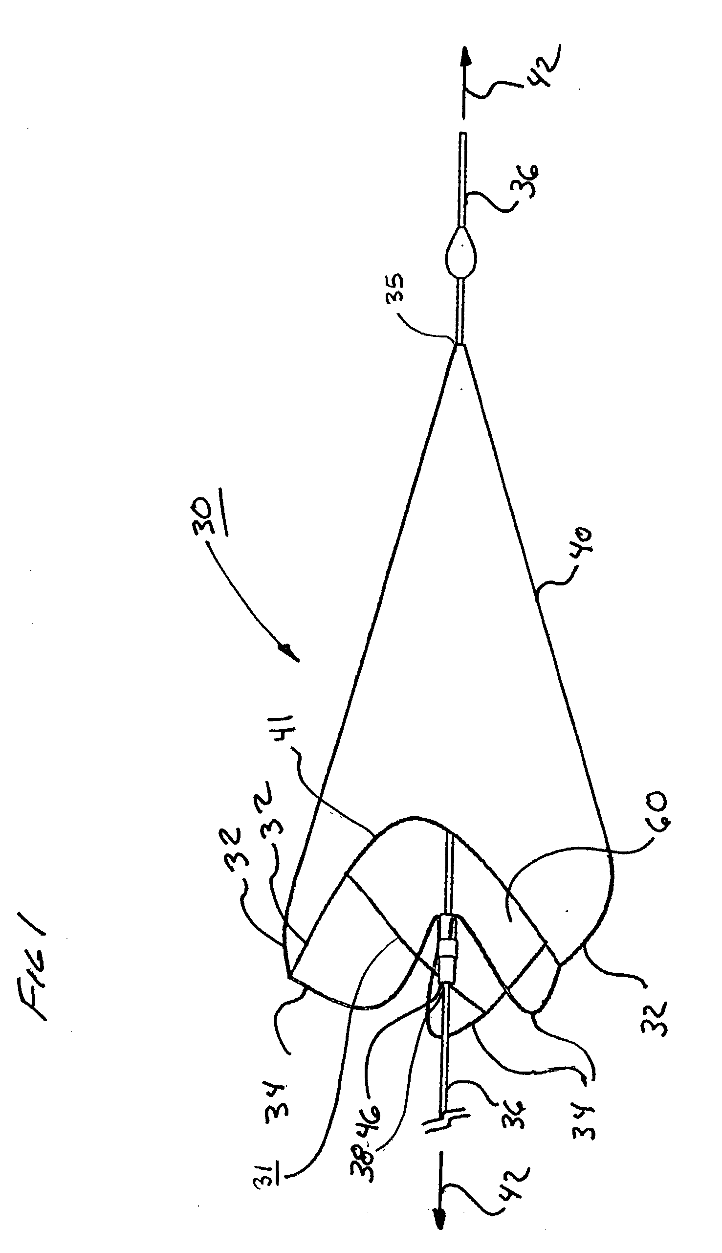
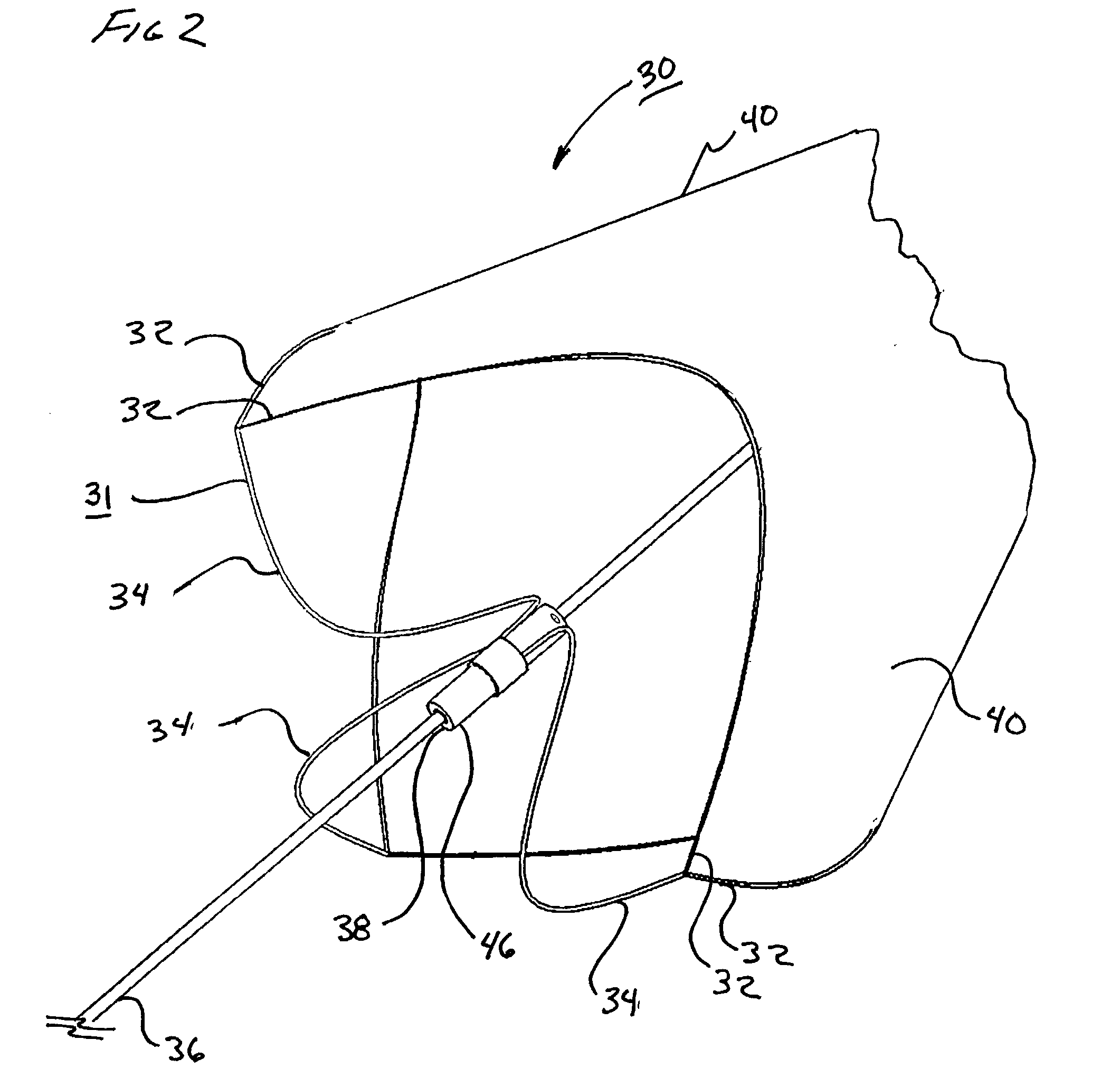
An improved embolic filter frame having looped support struts. The frame configuration provides enhanced longitudinal compliance, improved sealing against a vessel wall, low profile delivery, and a short deployed length. The looped support struts have a high degree of "radial" stiffness with a low degree of "longitudinal" stiffness. In the deployed state, the frame exerts a relatively high stress onto a vessel wall to maintain an effective seal, yet remains compliant in the longitudinal direction. Minor displacements of the support wire or catheter are therefore not translated to the filter. The looped support struts elongate when tensioned and assume a compressed and essentially linear form. While constrained in this linear state by a delivery catheter, the support struts exert minimal stress onto the delivery system. The overall delivery profile and stiffness are therefore reduced. When the delivery catheter constraint is removed during deployment, the struts "snap open" and assume a looped configuration which exert a high degree of force onto the vessel wall, creating an enhanced filter to vessel wall seal. In addition, the looped struts and the central collar connecting the support struts to the support wire, are positioned essentially within the plane of the filter opening. The overall deployed length of the embolic filter is therefore reduced.

Application Domain

Technology Topic

EngineeringLower degree +6

Image

  • Embolic filter frame having looped support strut elements
  • Embolic filter frame having looped support strut elements
  • Embolic filter frame having looped support strut elements

Examples

  • Experimental program(1)

Example

[0095] As shown in FIG. 15, a 0.9 mm nitinol tube 104, with a wall thickness of approximately 0.09 mm (obtained from SMA Inc, San Jose, Calif.) was laser cut by Laserage Technologies Inc, Waukegan, Ill., to form a frame configuration of a single, undulating, integral, 6 apex ring. The frame included radiopaque marker housings 106 at each distal apex and tether or strut elements 34 extending from each proximal apex 108 and converging at the opposite end in a "collar" 46 of uncut parent material. This frame was then lightly grit blasted at 30 psi with 20-micron silicon carbide media in a grit blasting machine (Model MB1000 available from Comco Inc, Burbank, Calif.). The frame was then gently slid up a tapered mandrel until it achieved a functional size of approximately 6mm.
[0096] The frame and mandrel were then subjected to an initial thermal treatment to set the geometry in an initial, tapered (conical) configuration in an air convection oven (Carbolite Corporation, Sheffield, England). The frame was quenched in ambient temperature water and removed from the mandrel, resulting in a non-inverted frame.
[0097] Shown in FIG. 16 is the non-inverted frame 110 having support struts 34, a central collar 46, apexes 108, and radiopaque marker housings 106. The frame portion distal to the apexes 108 form a filter element support portion 32. The frame was then placed on a second mandrel, designed to constrain the outside of the frame while allowing the inversion of the tether elements back upon themselves. Once constrained in the proper configuration, the tooling and frame were subjected to a second thermal treatment to set the final frame geometry and to set the nitinol transition to an appropriate temperature. The resulting inverted frame is depicted in FIG. 17.
[0098] Shown in FIG. 17 is an inverted frame 112 having six looped support struts 34a, apexes 108, radiopaque housings 106, and an integral central collar 46. The frame portion distal to the apexes 108 form a filter element support portion 32.
[0099] One skilled in the art will appreciate that variances in the filter frame material(s), dimensions, geometry, and/or processing can all be made to create alternate embodiments with varying desirable properties. For example, the relative position of the central collar 46 to the apexes 108 can be varied according to FIGS. 5C and 5D.
[0100] The frame (now at functional size and preferred geometry) was then lightly coated with fluorinated ethylene propylene (FEP) powder (e.g., FEP 5101, available from DuPont Corp, Wilmington, Del.) by first stirring the powder in a kitchen blender (Hamilton Beach Blendmaster) after the powder was mixed into a "cloud," the frame was lowered into the blender for approximately 5 seconds (enough time for FEP to build up onto the surface of the frame). The frame, coated with FEP powder, was placed in an air convection oven (Grieve Oven, The Grieve Corporation, Round Lake, Ill.) set at 320.degree. C. for approximately one minute followed by air cooling to room temperature.
[0101] A typical filtering media was made by laser perforating one layer of a thin, polytetrafluoroethylene (PTFE) membrane using a 10-watt CO.sub.2 laser. The membrane thickness measured about 0.0002" (0.005 mm) and had tensile strengths of about 49,000 psi (about 340 KPa) in a first direction and of about 17,000 psi (about 120 KPa) in a second direction (perpendicular to the first direction). The tensile measurements were performed at 200 mm/min. load rate with a 1" (2.5 cm) jaw spacing. The membrane had a density of about 2.14 g/cm.sup.3. The laser power and shutter time parameters were adjusted to allow the laser to consistently create uniform 0.004" (0.1 mm) diameter holes in the membrane. The hole pattern geometry was then adjusted to create a pattern with uniform hole size, uniform hole spacing, and uniform strength throughout the pattern. This perforated pattern was then folded on itself and heat-sealed using a local heat source (Weber soldering iron, EC2002M, (available through McMaster Carr, Santa Fe Springs, Calif.)) into a pattern which would result in a conical shape. The conical flat pattern was then trimmed with scissors, inverted, and mounted upon the FEP powder coated NiTi frame and attached though the application of localized heat (the heat causing the FEP coating on the frame to re-melt and flow onto the surface of the filter sack thus providing a biocompatable thermoplastic adhesive).
[0102] A guide wire component was then inserted into the collar end of the frame and a small amount of instant adhesive (Loctite 401, Loctitie Corp, Rocky Hill, Conn.) was applied and dried to adhere and create a smooth transition from the guide wire to the outer diameter (OD) of the frame collar. One skilled in the art will realize that attachment of the filter to the guide wire could be accomplished by adhesion, welding, soldering, brazing, a combination of these, or a number of other methods.
[0103] The resulting embolic filter is as shown and described above with respect to FIG. 1 et seq.
[0104] A further embodiment of the present invention is illustrated in FIGS. 18A through 18C. In this embodiment the filter assembly 30 includes a frame 31 that is slidably mounted to the support wire 36. This attachment may be accomplished through a variety of means, including by providing a collar 46 that is sized slightly larger than the support wire 36 to allow the collar to move relative to the support wire when in use. Stops 114a, 114b are provided on the support wire 36 to limit the range of relative movement between the filter assembly 30 and the support wire 36. Constructed in this manner, the filter assembly 30 has exceptional longitudinal compliance relative to the support wire in that the support wire can freely move between the stops 114 without translating longitudinal or rotational movement to the filter assembly. The full range of proximal and distal movement of the filter assembly 30 relative to the stops 114 is shown in FIGS. 18B and 18C.
[0105] While particular embodiments of the present invention have been illustrated and described herein, the present invention should not be limited to such illustrations and descriptions. It should be apparent that changes and modifications may be incorporated and embodied as part of the present invention within the scope of the following claims.

PUM

PropertyMeasurementUnit
Length
Force
Diameter
tensileMPa
Particle sizePa
strength10

Description & Claims & Application Information

We can also present the details of the Description, Claims and Application information to help users get a comprehensive understanding of the technical details of the patent, such as background art, summary of invention, brief description of drawings, description of embodiments, and other original content. On the other hand, users can also determine the specific scope of protection of the technology through the list of claims; as well as understand the changes in the life cycle of the technology with the presentation of the patent timeline. Login to view more.

Similar technology patents

Open-bottom automatic discharging tank device

InactiveCN101746580AImprove sealingRealize automatic unloadingFlexible coversWrappersCharge and dischargeCushion
Owner:TAIYUAN UNIVERSITY OF SCIENCE AND TECHNOLOGY

Classification and recommendation of technical efficacy words

  • Improve sealing

Variable frequency automated capacitive radio frequency (RF) dielectric heating system

InactiveUS20020047009A1Improve sealingLowering gap impedanceMeat/fish preservation by heatingDielectric heating circuitsRadio frequencyHeating system
Owner:THE STATE OF OREGON ACTING BY & THROUGH THE OREGON STATE BOARD OF HIGHER EDUCATION ON BEHALF OF OREGON STATE UNIV +1

Active grill shutter vane design and vehicle system

InactiveUS20130223980A1Minimal pressure dropImprove sealingWind motor controlPump componentsAirflowAerodynamics
Owner:SHAPE CORP
Why Eureka
Try Eureka