Antenna assembly

a technology of antenna arrays and components, applied in the field of antenna arrays, can solve the problems of complex manufacturing methods, high relative adjustment and precise positioning of individual material layers, and high cost of antenna arrays, and achieve the effects of facilitating the manufacturing process, reducing manufacturing costs, and improving shielding performan

Inactive Publication Date: 2004-06-17
ROBERT BOSCH GMBH
View PDF6 Cites 37 Cited by
  • Summary
  • Abstract
  • Description
  • Claims
  • Application Information

AI Technical Summary

Benefits of technology

0008] The antenna array according to the present invention, having the features of Claims 1 or 2, has the advantage over the known design approaches that the manufacturing process is facilitated, a more compact sensor is provided as well as excellent shielding from the electromagnetic energy or from energy waves in unwanted radiation directions.
0009] A compact and easy to manufacture antenna array results from an appropriate arrangement of the electrical connecting sections within the multi-layer carrier between the first potential surface and the second potential surface, as closely as possible underneath the first potential surface. If the connecting sections are correspondingly arranged as closely as possible underneath the first potential surface, the major part of the electromagnetic radiation may be forced upward via the coupling devic

Problems solved by technology

However, these antenna arrays have the disadvantage that the relative adjustment and the precise positioning of the individual material layers is highly complicated and difficult to implement.
As a result of the fairly complicated design and the involved manufacturing process it requires, such antenna arrays are quite expensive.
This approach has the disadvantage of requiring a complicated manufacturing method, since holes must be milled out and foams inserted.
In add

Method used


Image

  • Antenna assembly
  • Antenna assembly
  • Antenna assembly

Examples


Embodiment Construction

[0035] Identical reference numerals in the figures denote identical or functionally identical components.

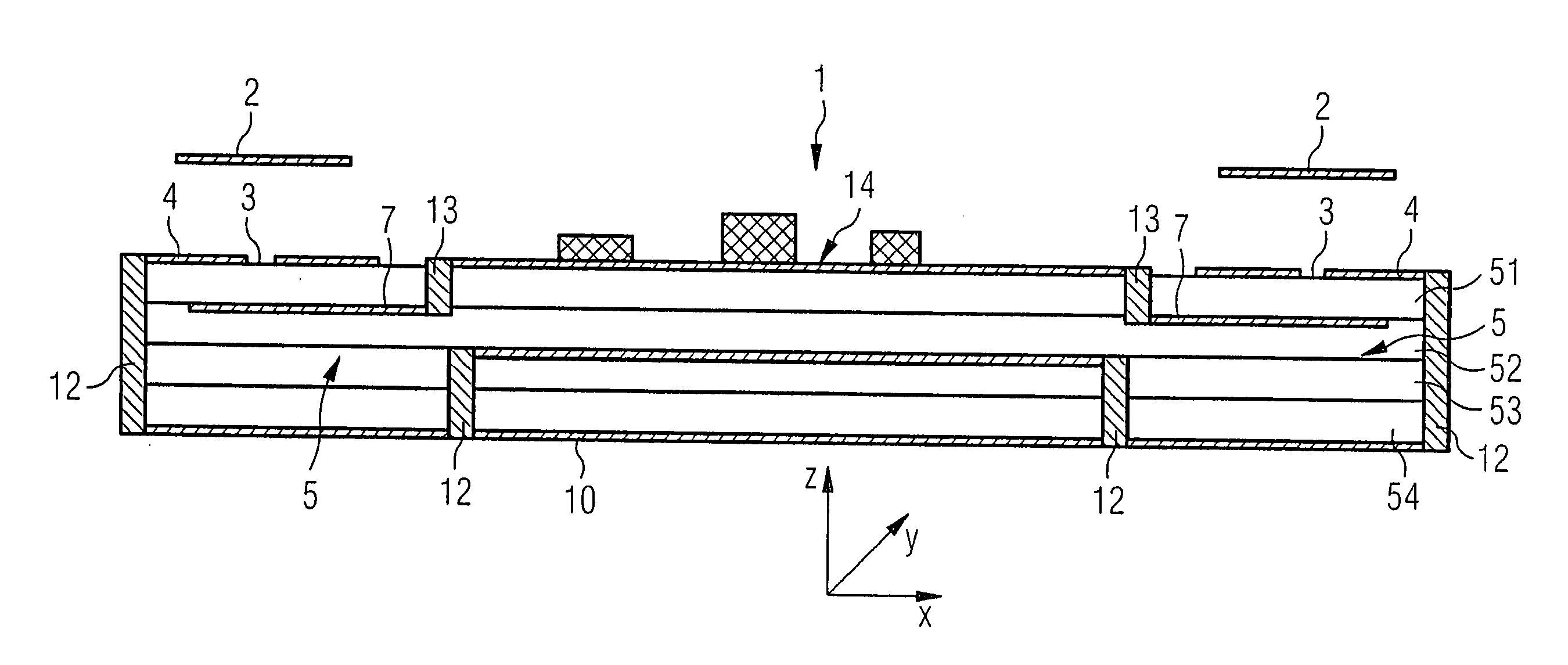
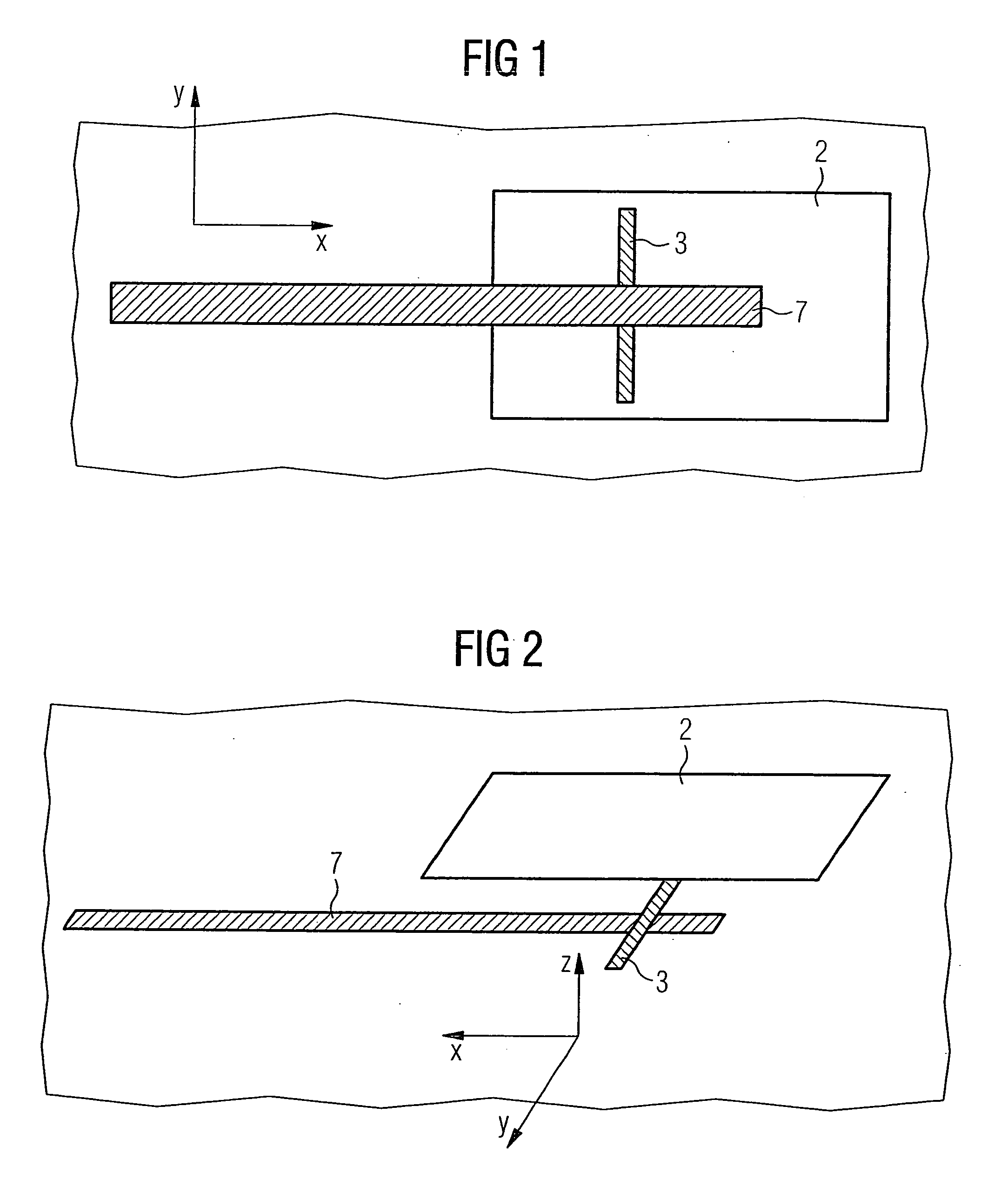
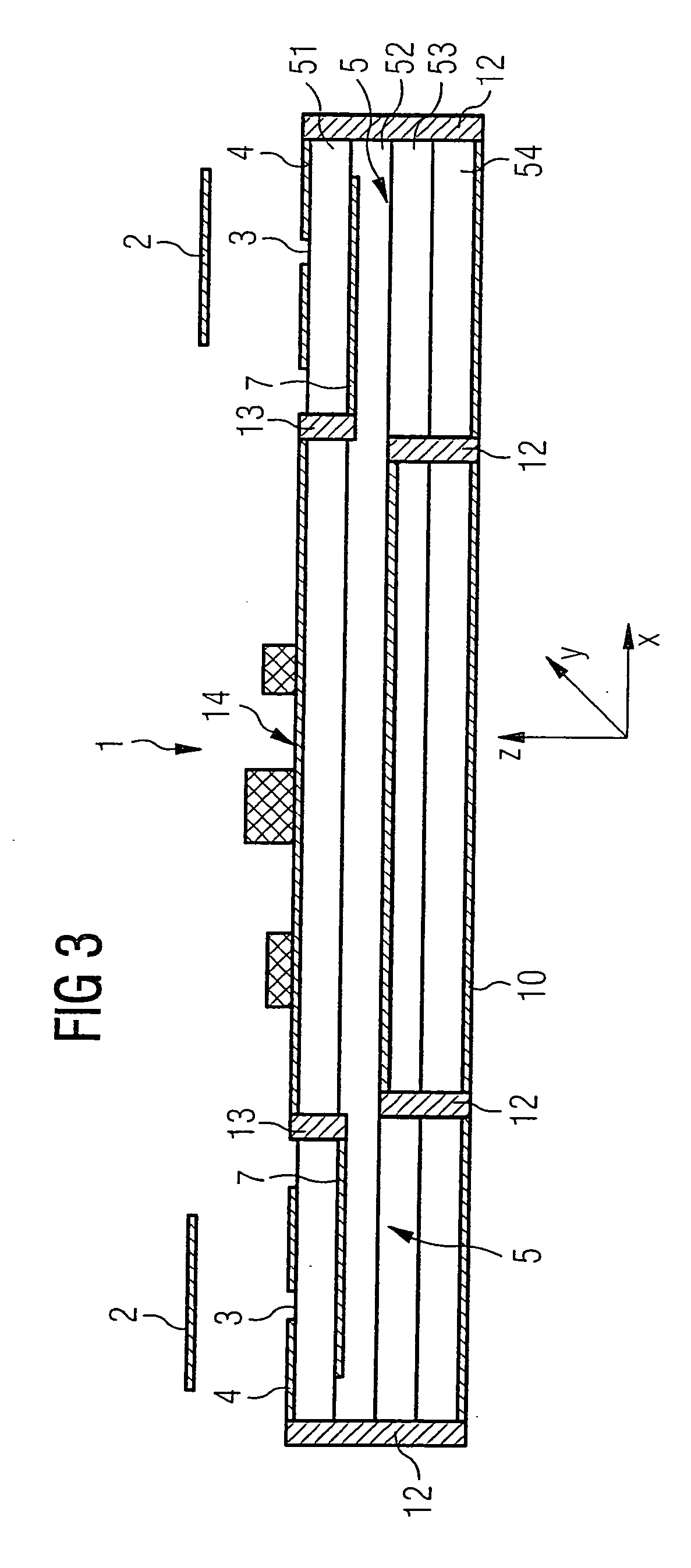
[0036] FIGS. 1 and 2 schematically show the arrangement of electrical connecting sections 7, in the form of feed lines 7, coupling devices 3, in the form of coupling slots 3, and transmission and / or receiving devices 2, in the form of radiator surfaces (so-called patches) 2. Such an array is called a slot-coupled patch antenna.

[0037] In FIGS. 1 and 2, the dielectric carrier (substrate) 5 and the first and second potential surfaces 4, 10, which are at ground, or ground planes 4, 10 have not been drawn in. The shown radiator surfaces 2 are either applied on a foam material or advantageously affixed on a housing top of the array (not shown).

[0038] The principle of a slot-coupled patch antenna will now be briefly discussed on the basis of FIGS. 1 and 2. Feed lines 7 are supplied with electromagnetic energy by a supply network device (not shown). Feed lines 7 are located underneath co...


PUM


Abstract

The present invention provides an antenna array for ascertaining the distance between vehicles and their speed, which includes devices for receiving or transmitting signal waves, a multi-layer carrier situated underneath the devices, a first potential surface, which is at ground and which is situated on the surface of the carrier facing the devices, coupling devices located in the first potential surface, electrical connecting sections disposed as closely as possible underneath the first potential surface, and a second potential surface which is located underneath the connecting sections and is at mass.

Description

BACKGROUND INFORMATION[0001] The present invention is directed to an antenna array and, in particular, a slot-coupled antenna array for ascertaining the distance between motor vehicles or their speed.[0002] Although able to be used in any field of application in the antenna sector, the present invention and the problem definition on which it is based are explained with reference to an antenna array on board a motor vehicle to ascertain the distance between motor vehicles or their speed.[0003] Systems are already known in which the distance and the speeds are measured by radar (microwaves), especially short-range radar. Currently, radiator-surface antenna arrays (patch antennas) are used, among others, in which radiator surfaces (patches) are mounted directly on substrate materials or on top of foam materials. The radiator surfaces are excited either on the antenna side by feed lines or by coupling slots. The feed lines may be accommodated on an additional material, which is a differ...

Claims


Application Information

Patent Timeline
IPC IPC(8): H01Q21/08H01Q1/32H01Q1/38H01Q1/52H01Q9/04H01Q13/08
CPCH01Q1/3233H01Q9/0457H01Q9/045H01Q1/523
Inventor GOTTWALD, FRANKVOIGTLAENDER, KLAUSTOENNESEN, TOREMOELLER, ANDREHAENSEL, JENS
Owner ROBERT BOSCH GMBH
Why Eureka
Try Eureka