Method for manufacturing a near net-shape mold

a manufacturing method and mold technology, applied in the field of mold manufacturing, can solve the problems of large lead time, large amount of manufacturing time, and large number of steps in the manufacturing process, and achieve the effect of reducing the number of steps and long lead time, and reducing the cost of manufacturing

Inactive Publication Date: 2004-07-01
STEWART DAVID H
View PDF6 Cites 149 Cited by
  • Summary
  • Abstract
  • Description
  • Claims
  • Application Information

AI Technical Summary

Problems solved by technology

Currently, the manufacturing of molds for use in the automotive, consumer products, appliance, computer, and consumer electronics industries is a tedious process involving numerous steps and long lead times. A few examples of parts that require molds are:
In both cases, the contours of the mold are rough cut out of hardened (usually R.sub.c 30-40) tool steel, which is a slow and expensive process requiring very large and powerful machining centers that can cost hundreds of thousands or even millions of dollars.
In both cases, getting from the part design to the fully roughed surface comprises a large portion of the manufacturing time.
The lead time on a casting for a large automotive mold can consume half of the production time, and roughing another 20%.
Machines that efficiently perform both operations are extremely expensive.
This is a slow process because the number of passes required is very high and the machine feeds must be kept low to ensure dimensional accuracy.
Finishing in this manner can consume up to 30% of the lead time.
Electrical discharge machining (EDM) is an alternate process that has proved very successful in finishing and even polishing of molds, but is not usually any faster than machining when applied to very large molds.
Even using modern methods, this is a very labor intensive process that can take from 15-20% of the lead time, depending on the surface finish requirements and finish machining quality.
A difficult process is the gun-drilling of the cooling or heating lines into the mold.
This increases the cost of the process considerably.
The difficulties that prevent further improvements with these techniques are that:
material can be removed from hardened steels only at a limited rate, resulting in long roughing cycles;
cooling lines are limited to straight paths and are difficult to drill.
These older CNC systems often limit the feeds to less than 1 m / min when complex surfaces requiring high accuracy are cut.
Moreover, these massive machines are also slow to change directions, usually accelerating at a rate of 0.1 g or less.
Unfortunately, HVM's are currently very large and expensive, costing as much as 10 times more than a conventional machine.
Smaller shops that have taken the leap into HVM may struggle with the technical differences from conventional machining, but they almost always report substantial cost savings and lead time reductions after an adjustment period.
One drawback of this process is that the finished mold may not have the same life as a comparable steel mold.
The drawback is that rework of the shell can take 4-5 weeks if it becomes necessary.
Most importantly, the lead time over conventional machining tends to be much shorter.
On the negative side, while these processes promise large advantages for smaller parts, none of them can be applied to larger molds.
In a 25 cm part dimension, this Would result in an error of 0.25 mm, 5-10 times the limits typically specified in a machined mold.
If finish machining is required on these molds, their cost and lead time advantages tend to disappear.
Additionally, the cost per kilogram of the rapid tooling materials tends to be much higher than cast or block steel, making these processes much more expensive for large molds.
decreased warpage and residual stresses

Method used


Image

  • Method for manufacturing a near net-shape mold
  • Method for manufacturing a near net-shape mold
  • Method for manufacturing a near net-shape mold

Examples


Embodiment Construction

[0081] Reference will now be made in detail to the present exemplary embodiments of the invention, which are illustrated in the accompanying drawings. Wherever possible, the same reference numbers will be used throughout the drawings to refer to the same or like parts.

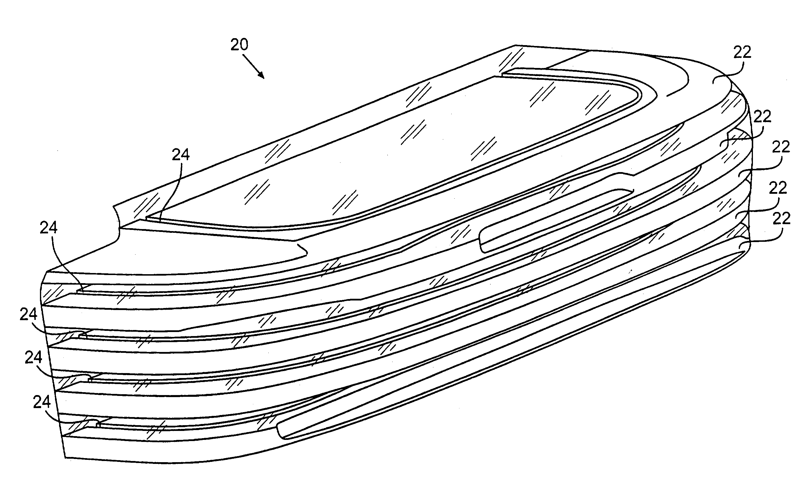
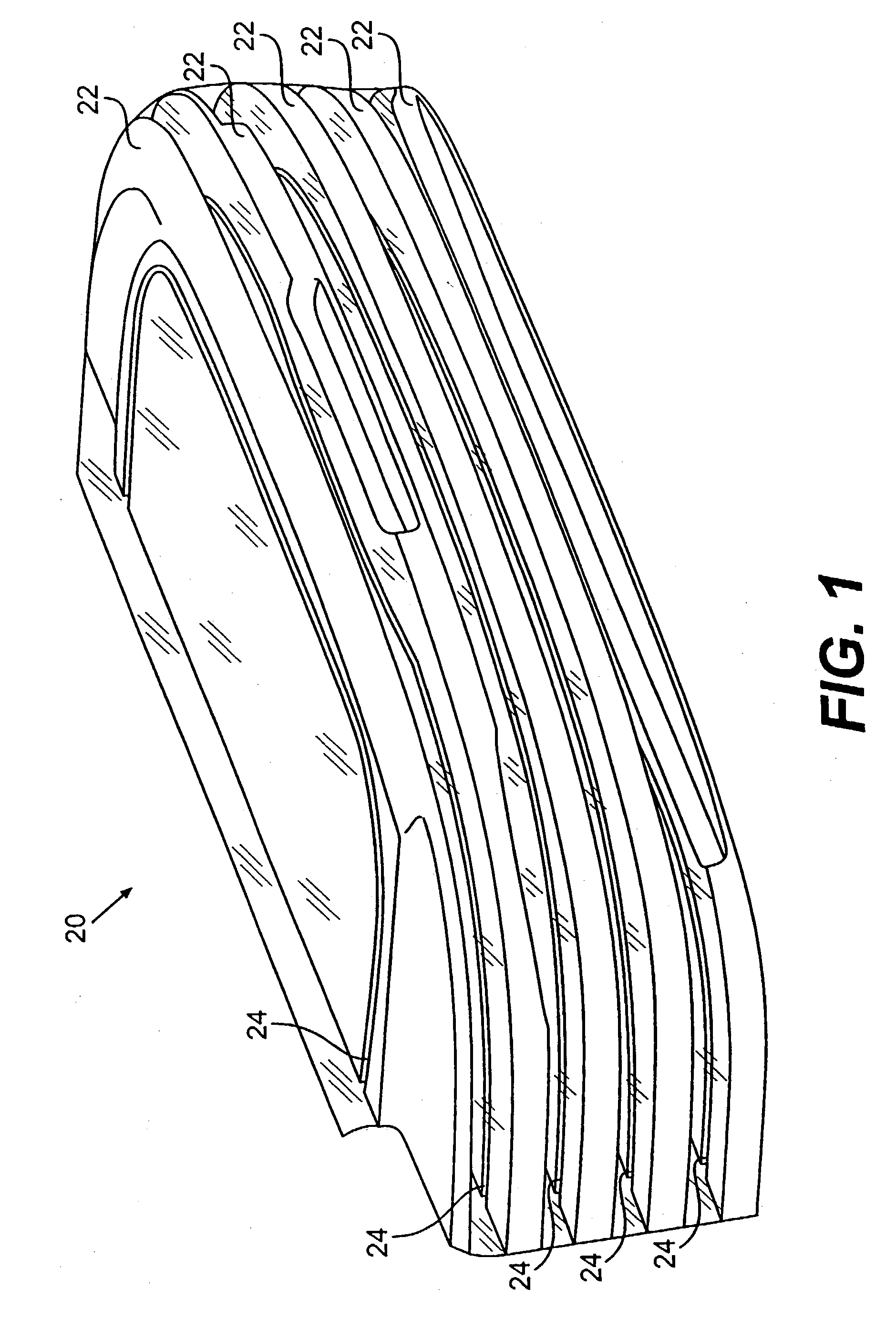
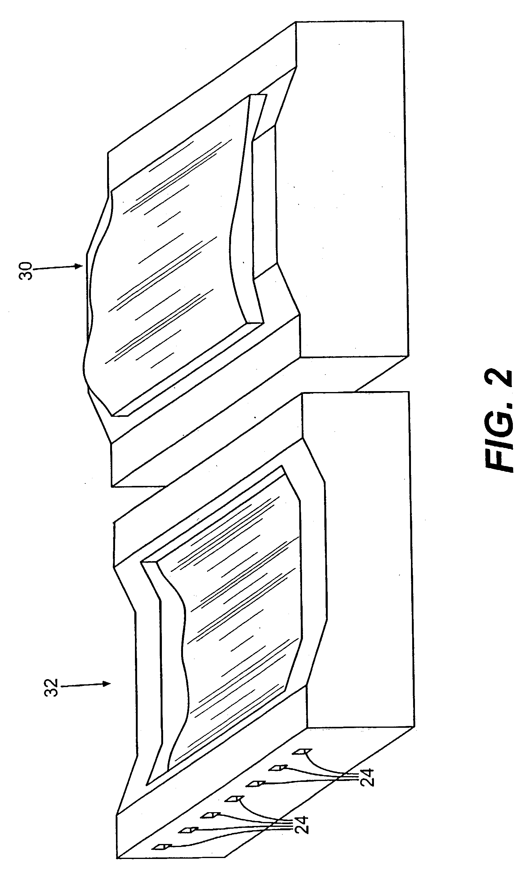
[0082] It is anticipated that the inventive process will substantially cut the lead times for manufacturing molds or mold portions, especially large molds but also for medium-sized molds or any mold with a complex geometry, while also providing improved part quality and shorter cycle times by allowing mold features that are unavailable with current techniques. The process could deliver a near net-shape mold or mold portion, ready for finish machining, to the mold maker in a fraction of the time it takes to cast or rough a mold cavity, providing a potential savings of materials and time. In one embodiment, the invention also could allow the incorporation of conformal heating / cooling lines. Such conformal heating / cooling...


PUM

PropertyMeasurementUnit
depthaaaaaaaaaa
spindle speedsaaaaaaaaaa
heightsaaaaaaaaaa

Abstract

A method for manufacturing a near net-shape mold from a weldable material, including creating a computer model of a mold portion (30,32), analytically sectioning the computer model of the mold portion into a plurality of mold zones (22), generating mold zone cutting paths for a cutting machine to follow, cutting the weldable material into plurality of mold zones, generating surface profile cutting paths for a cutting machine to follow, machining surface profiles into the mold zones, assembling the mold zones by placing the mold zones side-by-side, generating welding paths for an electron beam welding a machine to follow, and welding the mold zones together.

Description

[0001] 1. Field of the Invention[0002] The present invention relates to mold manufacturing. Specifically, the present invention relates to a process for manufacturing near net-shape molds by individually machining and subsequently joining mold segments together.[0003] 2. Description of the Related Art[0004] An examination of the techniques used to produce molding tools, or molds, will prove useful in demonstrating the benefits of the inventive process. Currently, the manufacturing of molds for use in the automotive, consumer products, appliance, computer, and consumer electronics industries is a tedious process involving numerous steps and long lead times. A few examples of parts that require molds are:[0005] automobile parts such as SMC or SRIM body or structural panels, and injection molded parts such as bumper covers, intake manifolds, dash trim, etc.;[0006] consumer products such as trash cans, laundry baskets, buckets, storage containers, etc.;[0007] appliances such as vacuum c...

Claims


Application Information

Patent Timeline
Patent Type & Authority Applications(United States)
IPC IPC(8): G05B19/4099G06F19/00
CPCG05B2219/49019G05B19/4099Y02P80/40
Inventor STEWART, DAVID H.
Owner STEWART DAVID H
Why Eureka
Try Eureka