
High frequency power detector with dBm-linear characteristic and method of regulating the power of an electrical HF-oscillation

a high-frequency power detector and linear characteristic technology, applied in the field of high-frequency power detectors, can solve the problems of disadvantageous .s. pat. no. 6,265,939, and the inability to realize known circuits with a relatively high production effort and expens

Active Publication Date: 2004-07-15
ATMEL GERMANY +1
View PDF9 Cites 2 Cited by
  • Summary
  • Abstract
  • Description
  • Claims
  • Application Information

AI Technical Summary

Benefits of technology

The invention is a high frequency power detector that is designed to detect and measure the power of electrical HF-oscillations. The detector is simple and does not require calibration or external temperature compensation. It uses a series circuit with a resistor and a second diode to produce a signal that is dependent on the power of the input HF-oscillation. This detector is advantageous because it is more linear in its response, which makes it easier to regulate the power of the HF-oscillation. The invention aims to overcome the disadvantages of previous methods and achieve additional advantages.

Problems solved by technology

However, at higher power levels, a non-linearity in this relationship arises, which must be compensated for.
The known circuit according to U.S. Pat. No. 6,265,939 is disadvantageous because it requires an active voltage source and a relatively large number of passive components.
For this reason, the known circuit can only be realized with a relatively high production effort and expense.
Moreover, the great number of necessary components requires a relatively large surface area of the circuit, which is especially disadvantageous in connection with an integration of such a circuit on a single chip.

Method used


Image

  • High frequency power detector with dBm-linear characteristic and method of regulating the power of an electrical HF-oscillation
  • High frequency power detector with dBm-linear characteristic and method of regulating the power of an electrical HF-oscillation
  • High frequency power detector with dBm-linear characteristic and method of regulating the power of an electrical HF-oscillation

Examples


Embodiment Construction

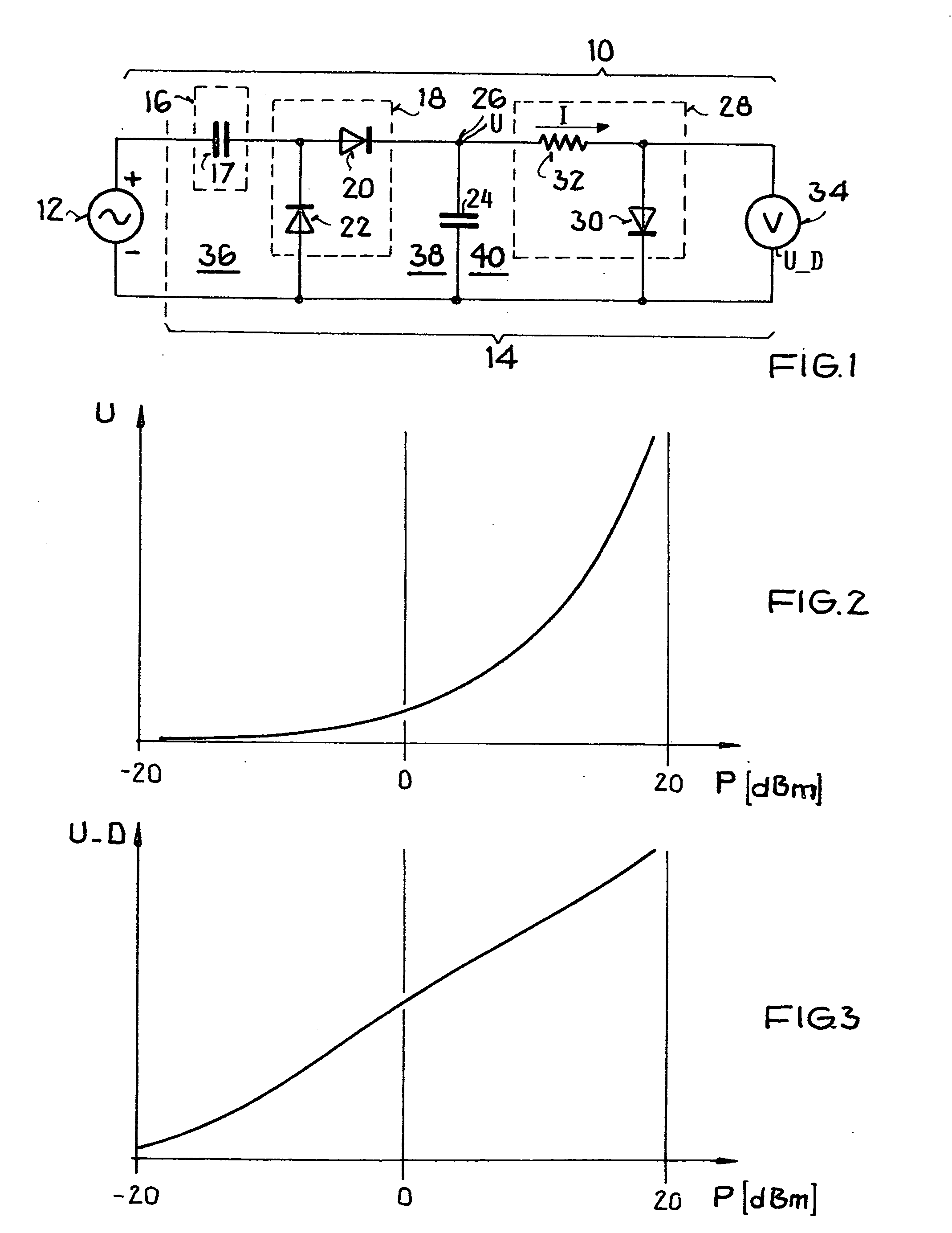
[0028] As schematically shown in FIG. 1, an overall high frequency (HF) circuit 10 includes an HF-voltage source 12 and an HF-power detector 14 according to the invention for detecting the HF-power output of the HF-voltage source 12. The HF-voltage source 12 may, for example, be realized as a collector oscillating circuit of a transistor. The inventive HF-power detector 14 comprises an input coupling arrangement 16, a peak value rectifier 18, a smoothing capacitor 24, an internal circuit node 26, a series circuit 28 forming an output stage, and a voltage tapping or detecting arrangement or means 34 such as a voltmeter or simply output terminals or taps. While it is not shown in FIG. 1, the circuit arrangement may be grounded or connected to a reference voltage at any suitable location. For example, the common conductor shown at the bottom of FIG. 1, which is connected to the negative side of the voltage source 12, could be grounded.

[0029] The input coupling arrangement 16, which com...


PUM


Abstract

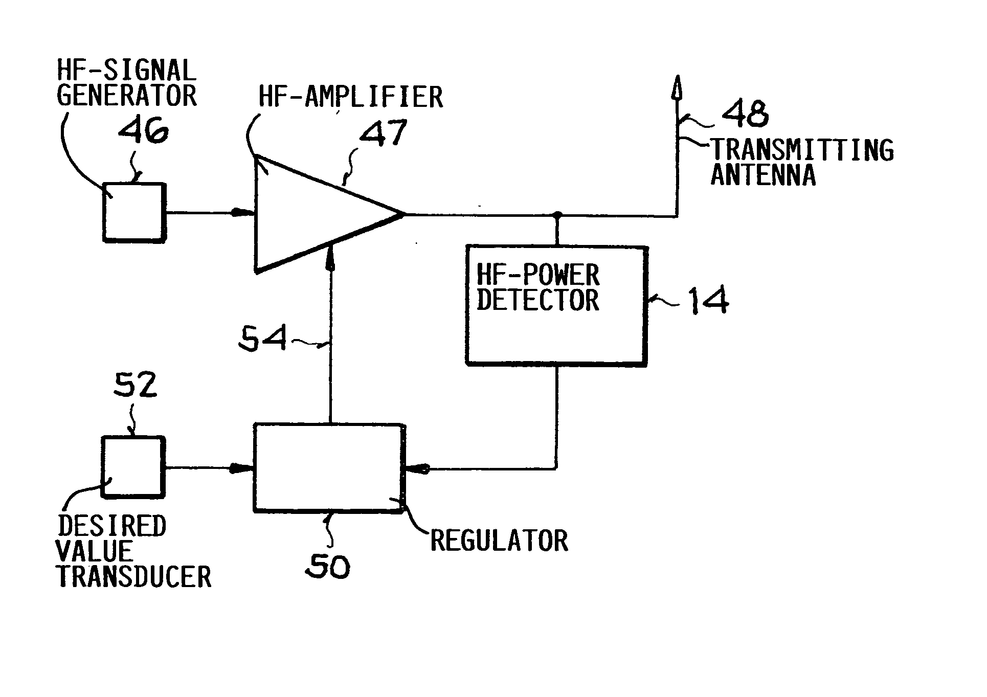
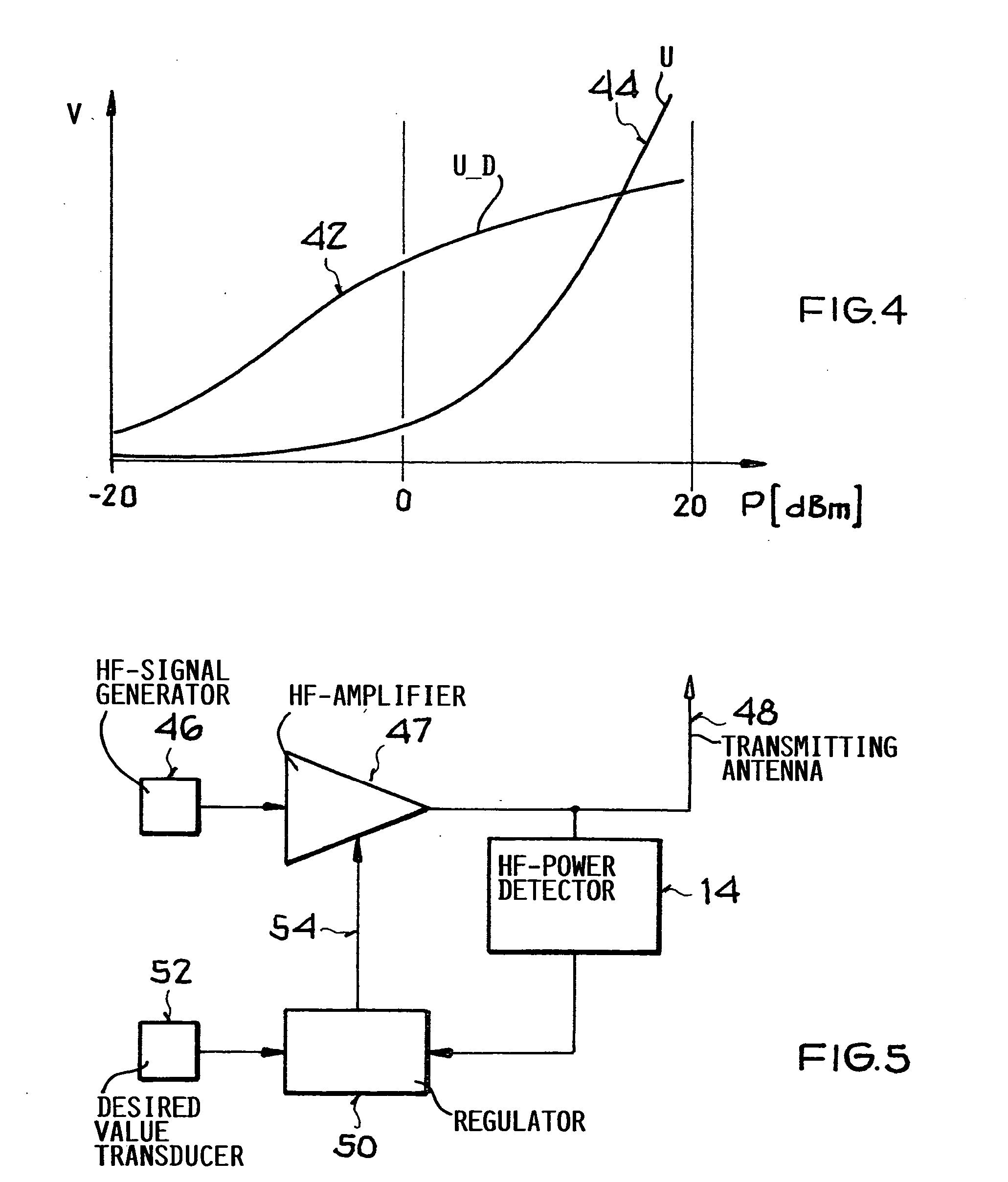
A high frequency power detector includes an input coupling arrangement that couples an electrical HF-oscillation into a basic circuit portion including at least a first diode and a circuit node. The power detector further includes a series circuit of a resistor and a second diode connected to the circuit node, as well as a voltage tapping arrangement for detecting or tapping the voltage drop across the second diode as an output signal. The voltage at the circuit node includes a DC component that depends on the power of the HF-oscillation. The output signal, i.e. the voltage drop of the second diode, has a linear voltage characteristic relative to the HF-power in dBm. A method of regulating the HF-power uses such a dBm-linear HF-power detector in a feedback loop for regulating the gain factor of an HF-amplifier.

Description

PRIORITY CLAIM[0001] This application is based on and claims the priority under 35 U.S.C. .sctn.119 of German Patent Application 102 60 749.4, filed on Dec. 23, 2002, the entire disclosure of which is incorporated herein by reference.[0002] The invention relates to a high frequency (HF) power detector with a linear characteristic in dBm, including an input coupling arrangement for coupling-in an electrical HF-oscillation. The invention further relates to a method of regulating the power of an electrical HF-oscillation using such a high frequency power detector.BACKGROUND INFORMATION[0003] A high frequency power detector and a power regulation method of the general type mentioned above, forming the field of this invention, is disclosed in U.S. Pat. No. 6,265,939 (Wan et al.).[0004] This Patent discloses a power regulation method in which the power is detected and used as an input signal for the power regulating circuit. In the scope of such a power regulation, it is desirable that th...

Claims


Application Information

Patent Timeline
Patent Type & Authority Applications(United States)
IPC IPC(8): G01R21/10G01R21/01H03G3/30
CPCH03G3/3042G01R21/10
Inventor KRUCK, ACHIM
Owner ATMEL GERMANY
Learn More