Carbon nanotube dispersion liquid and method for producing the same and polymer composite and method for producing the same

a technology of carbon nanotubes and dispersion liquids, which is applied in the field of carbon nanotube dispersion liquids and methods for producing the same, can solve the problems of insufficient development of the cylindrical network structure of carbon fibers to be used as structural materials with a diameter of several micrometers or more, the number of amorphous carbons being attached, and the failure of the manufacture of carbon nanotubes having the same structur

Inactive Publication Date: 2004-07-15
FUJIFILM BUSINESS INNOVATION CORP
View PDF4 Cites 68 Cited by
  • Summary
  • Abstract
  • Description
  • Claims
  • Application Information

AI Technical Summary

Problems solved by technology

However, the carbon fiber to be used as a structural material with a diameter of several micrometers or more is insufficient in development of its cylindrical network structure in parallel with an axis of a tube.
In many cases, however, there are a number of amorphous carbons being attached around the network structure.
Although the structure of the carbon nanotube can be somewhat determined by selecting an appropriate synthetic method and conditions thereof, the manufacture of only carbon nanotubes having the same structure has not yet been successful.
However, there are systems where carbon nanotubes cannot be dispersed from the beginning, causing hindrance in the applications of carbon nanotubes.
However, the carbon nanotube by itself has poor wettability and dispersibility with respect to a solvent, so that the polymer needs to be provided with a considerable concentration of carbon nanotube for increasing the dynamic strength of the polymer.
In this case, however, there is fear that the surfactant used as a dispersant may remain in the polymer composite to cause the migration of the surfactant with time, causing the polymer composite to be changed in quality.
Furthermore, when the surfactant used is ionic, there is a possibility that the electric characteristics of the obtained polymer composite such that the polymer can not be used for an electronic device.
However, such chemical modification involves a little-complicated process, such as the introduction of a silicone-based functional group.
It is also difficult to disperse the carbon nanotube directly and uniformly in the resin substrate even though the carbon nanotube has an increased compatibility with the resin substrate, so that much more dispersion energy is needed in mechanical stirring and so on.
In many cases, in spite of such an effort, there is obtained only a polymer composite in which an aggregate of carbon nanotube is unevenly dispersed.
It is difficult to secure a stable dispersion state of the carbon nanotube even though the carbon nanotube is directly dispersed in the polymer solution.
On the other hand, even if the polymer is mixed with the carbon nanotube dispersion liquid, the polymer cannot be easily dissolved or the dispersion stability of the carbon nanotube can be affected.
In other words, the MWNT loses its flexibility compared with the SWNT.
There is a tendency that the MWNT becomes inflexible and the reactivity thereof becomes sluggish as the MWNT becomes multi-layered.
In the case of SWNT or MWNT which is not of a sufficient multiple layer structure, the introduction of many functional groups may destroy the carbon nanotube structure itself.
Furthermore, if the introduction amount of the functional group is small, the dispersion stability of the dispersion liquid cannot be increased as a matter of fact.
In the present technical level, there is no quantitative method for determining the degree of chemical modification on the carbon nanotube.
However, in the case of using a stirrer having a strong shearing force of agitation, the carbon nanotube being contained may be cut or damaged, so that the dispersion is completed within a short time.
However, such an action is not sufficient for achieving satisfactory solubility of the polymer.
Thus, it becomes difficult to produce a uniform polymer composite because of insufficient dissolution.
In addition, such insufficient dissolution may affect the dispersion stability of the carbon nanotube at the time of dissolution.

Method used


Image

  • Carbon nanotube dispersion liquid and method for producing the same and polymer composite and method for producing the same
  • Carbon nanotube dispersion liquid and method for producing the same and polymer composite and method for producing the same
  • Carbon nanotube dispersion liquid and method for producing the same and polymer composite and method for producing the same

Examples


example 1

[0108] Materials:

[0109] (a) MWNT (95% in purity, manufactured by Science Laboratory Co., Ltd.) . . . 0.02 g

[0110] (b) Concentrated nitric acid (60% by mass) . . . 14 g

[0111] (c) Pyridine

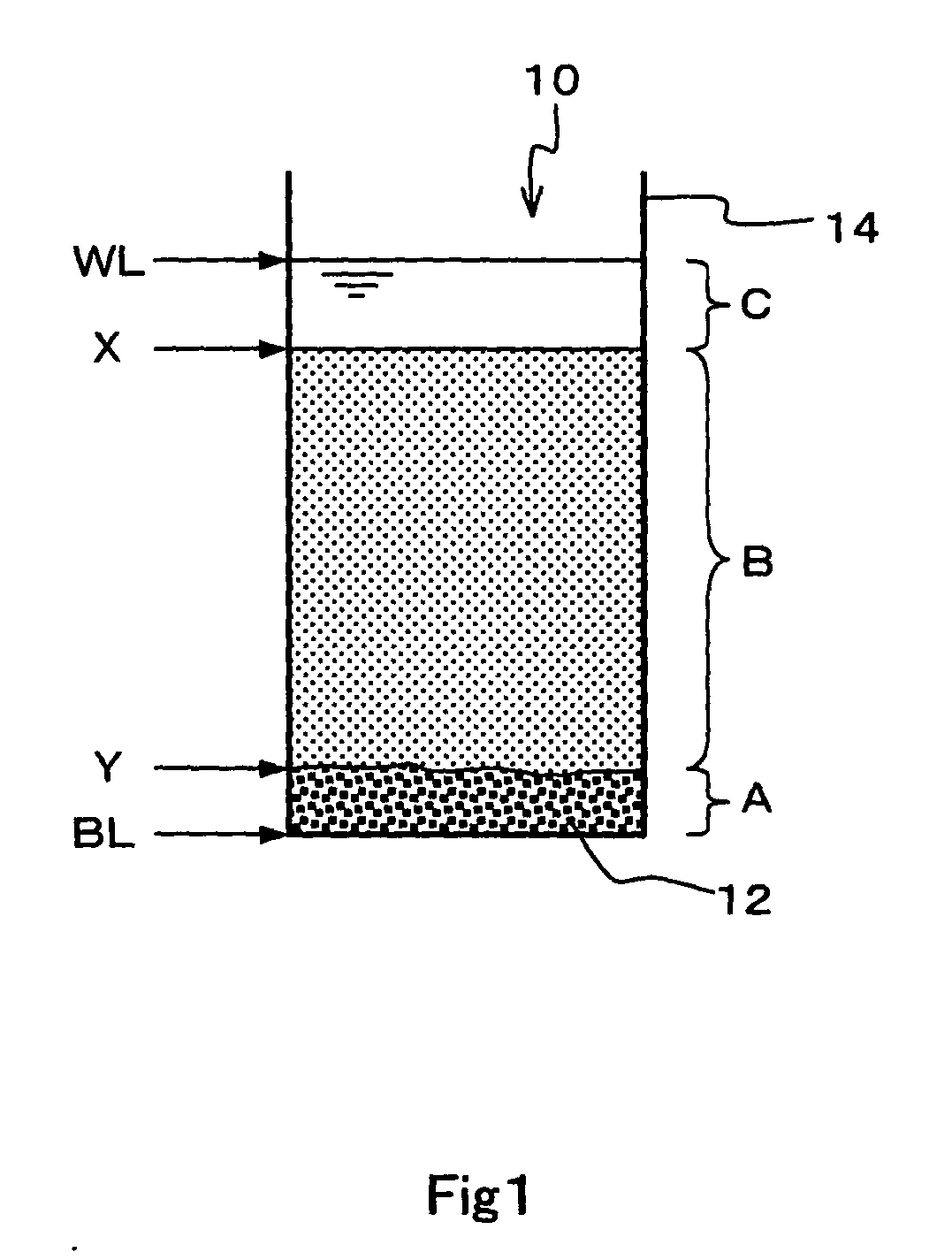
[0112] First of all, a carbon nanotube was ground with a mortar for 5 minutes in advance to make the surface of the carbon nanotube to be easily reacted, and then a mechano-chemical force was applied thereon. The carbon nanotube was added to the concentrated nitric acid and then the mixture was refluxed in an oil bath (120.degree. C.) for 4 hours. After that, centrifugation and decantation were repeated until the pH of the supernatant shifted to neutral (pH=6 or more), Subsequently, the resulting dispersion liquid was dried up and the modified carbon nanotube (aggregation) was obtained (the addition process so far). Here, the carboxyl group of the modified carbon nanotube released as the pH shifted to neutral that increases dispersibility of the carbon nanotube. Therefore, in the present example, cen...

example 2

[0117] Materials:

[0118] (a) MWNT (95% in purity, manufactured by Science Laboratory Co., Ltd.) . . . 0.02 g

[0119] (b) Concentrated nitric acid (60% by mass) . . . 14 g

[0120] (c) Pyridine

[0121] First of all, in the same manner as in Example 1, a mechano-chemical force was applied to a carbon nanotube. The carbon nanotube was added to the concentrated nitric acid and then the mixture was refluxed in an oil bath (120.degree. C.) for 4 hours. After that, in the same manner as in Example 1, when the pH of the supernatant shifted to neutral, the resulting dispersion liquid was dried and then the aggregation of a carbon nanotube carboxylic acid was obtained (addition process so far).

[0122] The obtained condensation of the carbon nanotube carboxylic acid was added to pyridine so as to be 0.1% by weight, and then the mixture was dispersed in the same manner as in Example 1. Consequently, a carbon nanotube dispersion liquid of Example 2 was prepared (Dispersion process, so far).

[0123] FIG. 5 ...

example 3

[0139] Materials:

[0140] (a) MWNT (95% in purity, manufactured by Science Laboratory Co., Ltd.) . . . 0.02 g

[0141] (b) Concentrated nitric acid (60% by mass) . . . 14 g

[0142] (c) U-Varnish-A (A 20% by mass solution of polyimide precursor in N-methyl pyrrolidone, manufactured by Ube Industries, Co., Ltd.) . . . 0.56 g

[0143] (d) Pyridine

[0144] (Preparation of Mixture Solution)

[0145] The carbon nanotube dispersion liquid (1 g) obtained in Example 1 was mixed with 0.56 g of U-Varnish-A and the resultant solution was stirred well with a magnetic stirrer, followed by defoaming the resulting mixture in vacuum for 60 minutes to prepare a mixture solution.

[0146] (Volatilization)

[0147] The obtained mixture solution was used and about 0.5 ml of the mixture solution was dropped on one side of a glass substrate using a Pasteur pipette to form a cast coat. Then, the glass substrate was heated at 210.degree. C. for 60 minutes to volatilize the solvent, forming a film on the glass substrate. Further...


PUM

PropertyMeasurementUnit
diameteraaaaaaaaaa
lengthaaaaaaaaaa
lengthaaaaaaaaaa

Abstract

By employing a method of producing a carbon nanotube dispersion liquid, in which a carbon nanotube modified with a basic or acidic functional group is dispersed in a polar solvent having a polarity opposite to a polarity of the functional group, there is provided a carbon nanotube dispersion liquid having a high dispersion stability, in which a carbon nanotube is uniformly dispersed without using any surfactant or the like. By using the carbon nanotube dispersion liquid, a polymer composite in which a carbon nanotube is uniformly dispersed without being mixed with an impurity can be provided. In addition, a method for producing the polymer composite by relatively simple procedures is also provided.

Description

FIELD OF THE INVENTION AND RELATED ART STATEMENT[0001] The present invention relates to a carbon nanotube dispersion liquid useful for devices, functional materials, other structural materials, and the like, each containing the carbon nanotube as a main component, and to a method for producing such a carbon nanotube dispersion liquid. In addition, the present invention relates to a polymer composite in which a carbon nanotube is used as filler, and to a method for producing the polymer composite.[0002] Developments of the present invention are expected to be spread out in the fields of spacecrafts, portable electronic devices, clothing items, and the like, which require lightweight and strong polymer composite. However, it is conceivable that applications of the carbon nanotube may be expanded in other extensive fields.[0003] A fibrous carbon structure is generally called a carbon fiber. However, the carbon fiber to be used as a structural material with a diameter of several microme...

Claims


Application Information

Patent Timeline
Patent Type & Authority Applications(United States)
IPC IPC(8): B82B1/00C08J3/02C08J5/00C08K7/06C08K9/00C08L101/00D01F9/127D01F11/12
CPCB82Y30/00B82Y40/00C01B31/0273D01F11/12C08J5/005C08K9/00D01F9/127C01B2202/28C01B32/174
Inventor YOSHIZAWA, HISAEWATANABE, HIROYUKI
Owner FUJIFILM BUSINESS INNOVATION CORP
Why Eureka
Try Eureka