Chemical reaction apparatus and power supply system

a technology of power supply system and chemical reaction, which is applied in the direction of lighting and heating apparatus, sustainable manufacturing/processing, separation processes, etc., can solve the problems of increasing thermal energy loss and worsening energy utilization, so as to reduce the loss of thermal energy required for heating for power generation, improve energy utilization, and suppress thermal energy loss

Inactive Publication Date: 2004-08-05
CASIO COMPUTER CO LTD
View PDF20 Cites 40 Cited by
  • Summary
  • Abstract
  • Description
  • Claims
  • Application Information

AI Technical Summary

Benefits of technology

[0013] The present invention has the advantage that in a chemical reaction apparatus which includes a flow path for allowing fluid to flow and causes a heating element to heat the interior of the flow path to perform a desired chemical reaction, the energy utilization is improved by suppressing the thermal energy loss caused when the thermal energy generated by the heating element is partially radiated outside. The present invention also has the advantage that when this chemical reaction apparatus is applied to a power supply system using a fuel reforming type fuel cell, the loss of thermal energy required for heating for power generation can be reduced, the energy utilization can be increased, and the power supply system can be downsized.
[0014] To obtain the above advantages, a chemical reaction apparatus according to one aspect of the present invention comprises a plurality of substrates bonded to each other, at least one flow path formed in at least one of the plurality of substrates, heating element formed on at least one surface of at least one of the plurality of substrates to heat the flow path, and a heat radiation preventing film which covers at least a portion of an outermost surface of the plurality of substrates. The heat radiation preventing film can suppress radiation of heat from the outer surface of the substrate.
[0015] This chemical reaction apparatus further comprises a box member which covers all the outermost surfaces of the plurality of substrates including the heat radiation preventing film, wherein a space is formed in at least a portion between the box member and the outermost surfaces of the plurality of substrates including the heat radiation preventing film. The space is kept in a substantially vacuum state, or a gas having thermal conductivity lower than that of components of the box member is sealed in the space, so heat conduction to the outside from the outer surface of the substrate including the heat radiation preventing film can be suppressed. Accordingly, it is possible to suppress the thermal energy loss when the heating element heats the interior of the flow path, and increase the energy utilization.
[0020] When the chemical reaction apparatus of the present invention is applied to a power supply system including a fuel reforming type fuel cell, it is possible, as a fuel vaporizer, to supply an aqueous solution of methanol as power generation fuel to the flow path, and vaporize the fluid in the flow path by heating the flow path by the heating element. As a reforming unit, it is possible to form a reforming catalyst layer in the flow path, and reform the power generation fuel in the flow path by heating the flow path by the heating element, thereby produce hydrogen. As a carbon monoxide removing unit, it is possible to form a selective oxidation catalyst layer in the flow path, and remove carbon monoxide from a gas mixture containing carbon monoxide by heating the flow path by the heating element. Electric power can be generated by supplying hydrogen produced by these units to the fuel cell, and causing hydrogen and oxygen to react with each other. It is also possible to form a heat radiation preventing film which covers the outermost surfaces of the plurality of substrates of the chemical reaction apparatus, and further comprises a box member which covers all the outermost surfaces of the plurality of substrates including the heat radiation preventing film, and forms, around the outermost surfaces of the plurality of substrates including the heat radiation preventing film, a space which is in a substantially vacuum state or in which a gas having low thermal conductivity is sealed. In this manner, it is possible to reduce the loss of thermal energy required for heating for power generation, increase the energy utilization, and downsize the power supply system.

Problems solved by technology

This increases the thermal energy loss and worsens the energy utilization.

Method used


Image

  • Chemical reaction apparatus and power supply system
  • Chemical reaction apparatus and power supply system
  • Chemical reaction apparatus and power supply system

Examples


first embodiment

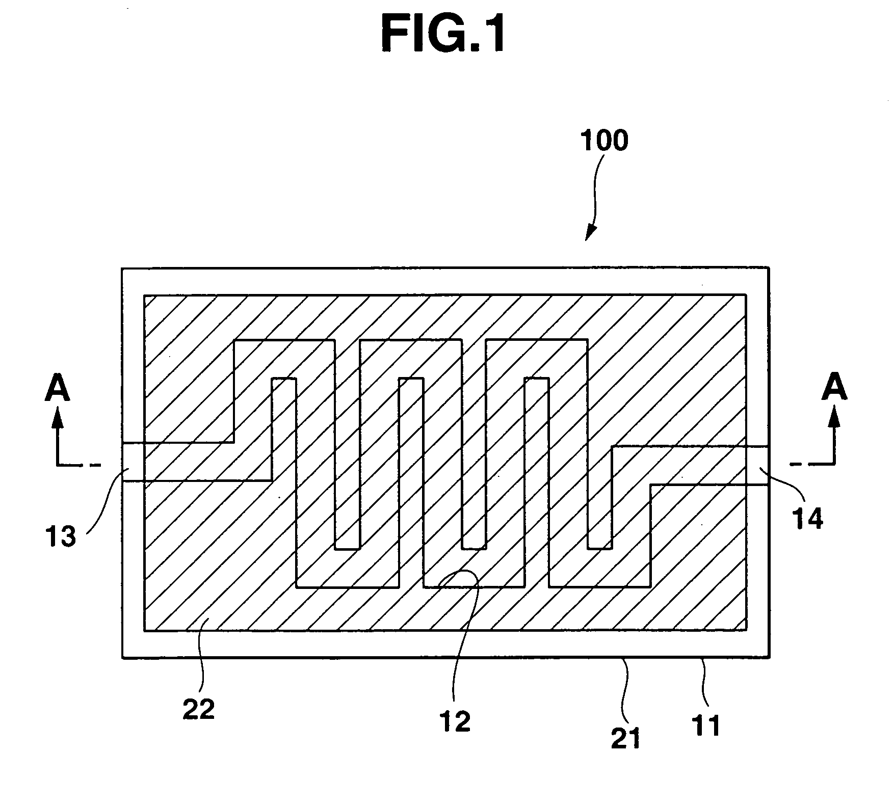
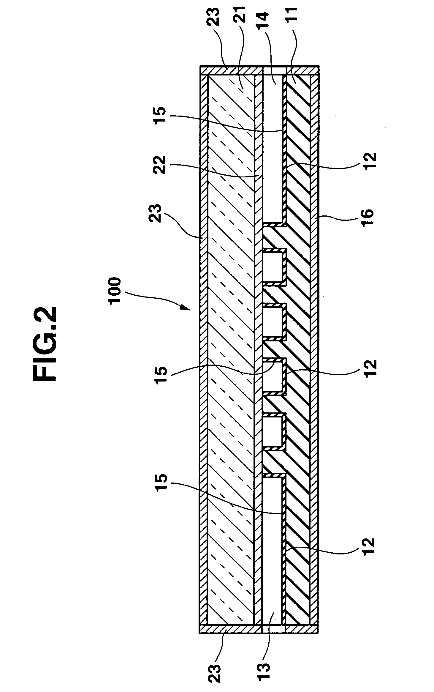
[0041] FIG. 1 is an opened-up plan view as a chemical reaction apparatus 100 according to the present invention. FIG. 2 is a sectional view taken along a line A-A of this chemical reaction apparatus 100. FIG. 3 is a sectional view showing an example of the packaged state when the chemical reaction apparatus 100 according to the present invention is applied to an arbitrary system.

[0042] The chemical reaction apparatus 100 of the first embodiment of the present invention includes a rectangular, plate-like first substrate 11 having at least a flat upper surface and made of silicon. For example, the first substrate 11 has a length of about 15 to 35 mm, a width of about 10 to 25 mm, and a thickness of about 0.4 to 1.0 mm. In one surface, i.e., the upper surface of the first substrate 11, a fine zigzagged flow path 12 is formed by using the micropatterning technology developed in the semiconductor fabrication technology. For example, the flow path 12 has a width of about 0.2 to 0.8 mm, a ...

second embodiment

[0056] FIG. 4 is an opened-up plan view, similar to the first embodiment shown in FIG. 1, as the second embodiment of a chemical reaction apparatus 100 according to the present invention. FIG. 5 is a sectional view, similar to FIG. 2, taken along a line B-B of this chemical reaction apparatus 100.

[0057] The second embodiment differs from the arrangement of the first embodiment in that a thin-film heater 22 formed on that surface of a second substrate 21, which opposes a first substrate 11 is formed into a zigzagged shape corresponding to a flow path 12 as shown in FIG. 4, and this thin-film heater 22 has a width smaller than that of the flow path 12 so as to be accommodated in the flow path 12 as shown in FIG. 5.

[0058] In this arrangement, the thin-film heater 22 can be further approached to a reaction catalyst layer in the flow path 12, compared to the arrangement of the first embodiment described above. Therefore, the efficiency of supply of the thermal energy to the flow path 12 ...

third embodiment

[0064] FIG. 6 is a sectional view, similar to FIG. 2, as the third embodiment of a chemical reaction apparatus 100 according to the present invention.

[0065] In this third embodiment, a thin-film heater 22 is formed on that surface of a second substrate 21, which faces a first substrate 11, as in the first embodiment described above. The third embodiment differs from the arrangement of the first embodiment in that an insulating film 24 made of silicon nitride or silicon oxide is additionally formed on that surface of the second substrate 21, which opposes the first substrate and includes the thin-film heater 22 embedded in the film 24, thereby forming a flat surface including the thin-film heater 22 on that surface of the second substrate 21, which opposes the first substrate 11.

[0066] As in the second embodiment described above, the thin-film heater 22 is formed into a zigzagged shape corresponding to a flow path 12. The second substrate 21 is adhered (bonded) to one surface of the ...


PUM

PropertyMeasurementUnit
pressureaaaaaaaaaa
pressureaaaaaaaaaa
thicknessaaaaaaaaaa

Abstract

A chemical reaction apparatus includes a solid body which has an outer surface, and in which at least one flow path which allows a chemical medium to flow is formed. This body has a heating element which heats the chemical medium in the flow path to accelerate a chemical reaction of the chemical medium, and a heat radiation preventing film which covers at least a portion of the outer surface of the body, and prevents radiation of heat generated by the heating element from a portion of the outer surface.

Description

[0001] The present invention relates to a chemical reaction apparatus and a power supply system including this chemical reaction apparatus and, more particularly, to a chemical reaction apparatus applied to a power supply system including a fuel cell which generates electric power by using fuel.[0002] In the technical field of chemical reactions, chemical reaction apparatuses are known in which various fluidized material mixtures are supplied to flow paths to cause chemical reactions, i.e., catalyst reactions with catalysts placed in the flow paths, thereby producing desired fluid materials.[0003] These chemical reaction apparatuses have various scales and structures in accordance with their applications. For example, in a certain relatively small-sized chemical reaction apparatus, a micron-order or millimeter-order flow path is formed in a silicon substrate by using the micropatterning technology developed in the technology for fabricating semiconductors such as semiconductor integ...

Claims


Application Information

Patent Timeline
Patent Type & Authority Applications(United States)
IPC IPC(8): B01J3/03B01J19/00B01J19/24B01J3/00C01B3/32C01B3/38C01B3/48F28F3/04F28F13/18H01M8/04H01M8/06H01M8/12
CPCB01J19/0093Y02E60/50B01J2219/00828B01J2219/00835B01J2219/00873C01B3/323C01B3/384C01B3/48C01B2203/0233C01B2203/0283C01B2203/044C01B2203/047C01B2203/066C01B2203/0811C01B2203/0822C01B2203/085C01B2203/1223C01B2203/1288C01B2203/82F28F3/048F28F13/18H01M8/0618H01M8/0625H01M8/0668Y02E60/523B01J19/249Y02P20/10H01M8/02F28F3/04
Inventor YAMAMOTO, TADAONAKAMURA, OSAMUTAKEYAMA, KEISHITERAZAKI, TSUTOMU
Owner CASIO COMPUTER CO LTD
Why Eureka
Try Eureka