Rotary internal combustion engine

a technology of internal combustion engine and rotary piston, which is applied in the direction of combustion process, engine cooling apparatus, turbine/propulsion fuel heating, etc., can solve the problem of reducing the energy consumption of air compression, and achieve the effect of low energy consumption and higher efficiency

Inactive Publication Date: 2004-08-12
STANEVICIUS ALGIMANTAS ALEKSANDRAS
View PDF4 Cites 8 Cited by
  • Summary
  • Abstract
  • Description
  • Claims
  • Application Information

AI Technical Summary

Benefits of technology

0018] According to the invention a low consumption of energy for air compression, a good heat exchanging process, by covering the combustors and the gas stream channels with the compressed air supply channels, a heat saving with thermal isolation of the power housing and the power body, an intermittent combustion process in the closed combustors, what permits considerably to arise the gas temperature and the fuel converting to a gas allows to expect, that a rotary combustion engine will be at least 1.5-2 times higher efficiency compare with the prototypes.

Problems solved by technology

This arrangement considerably decreases the energy consumption for air compression and it is smaller than conventional centrifugal compressors.

Method used


Image

  • Rotary internal combustion engine
  • Rotary internal combustion engine
  • Rotary internal combustion engine

Examples


Embodiment Construction

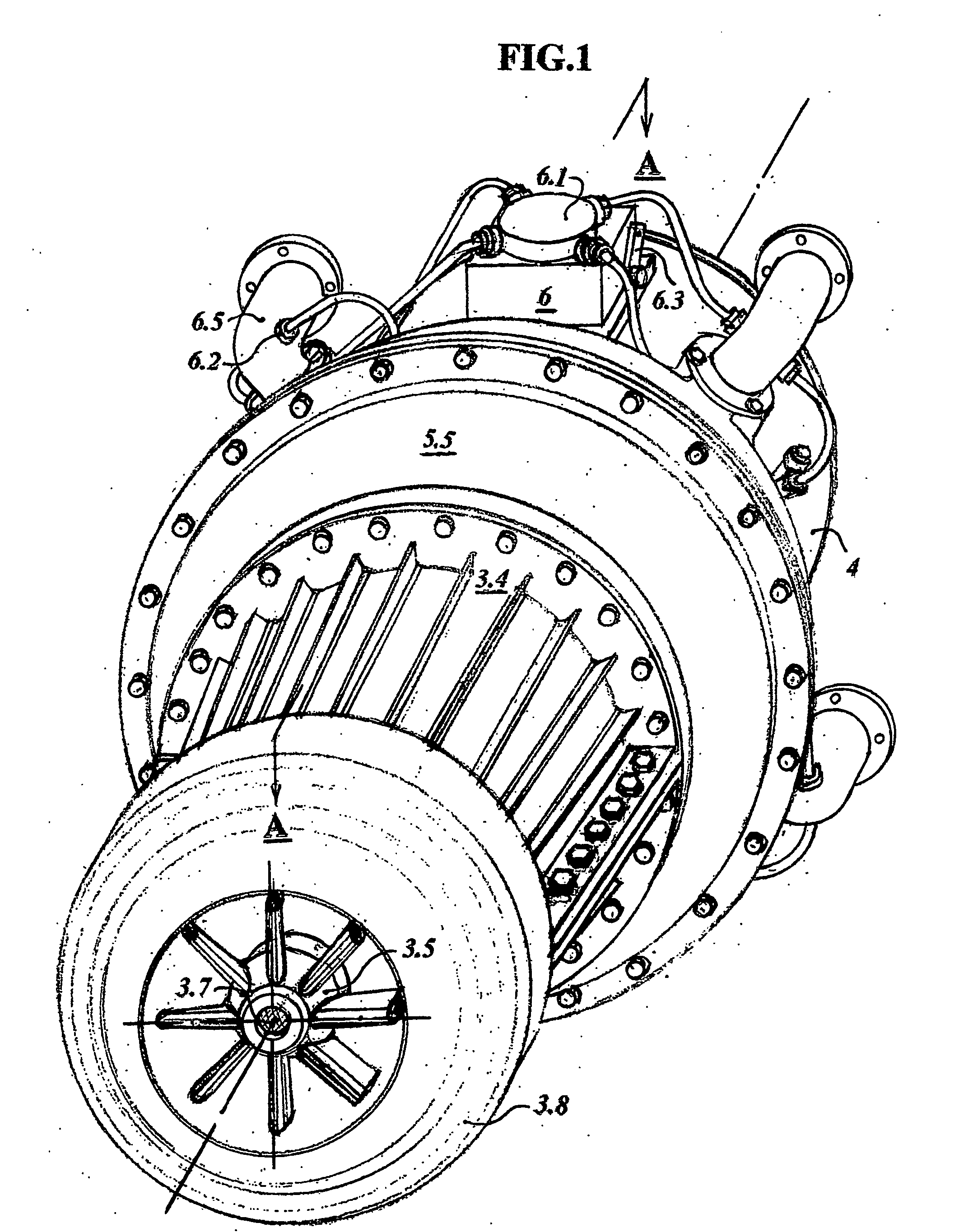
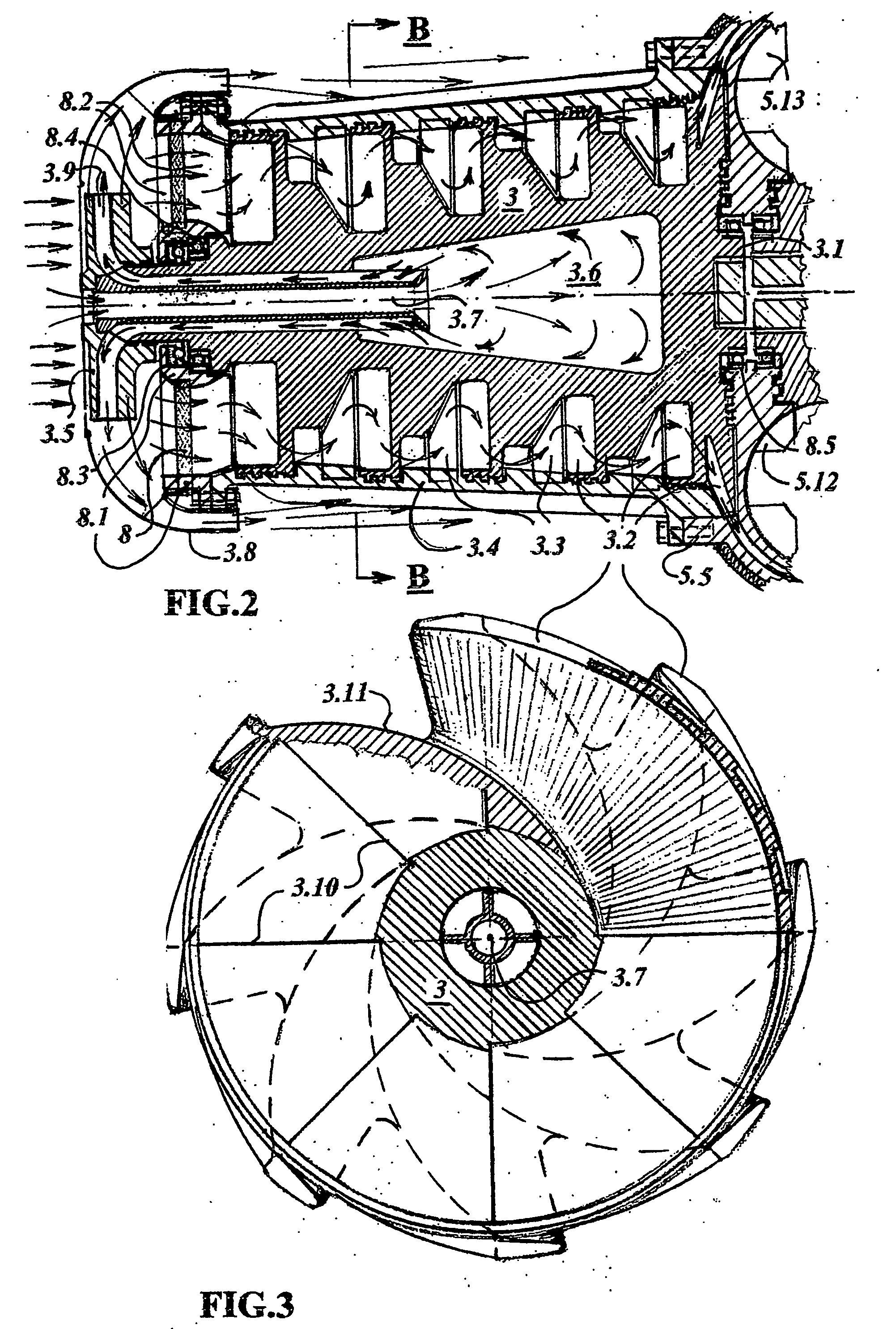
[0025] In FIGS. 1 to 5 is alone embodiment of a rotary internal combustion engine according to the invention and designated by the reference.

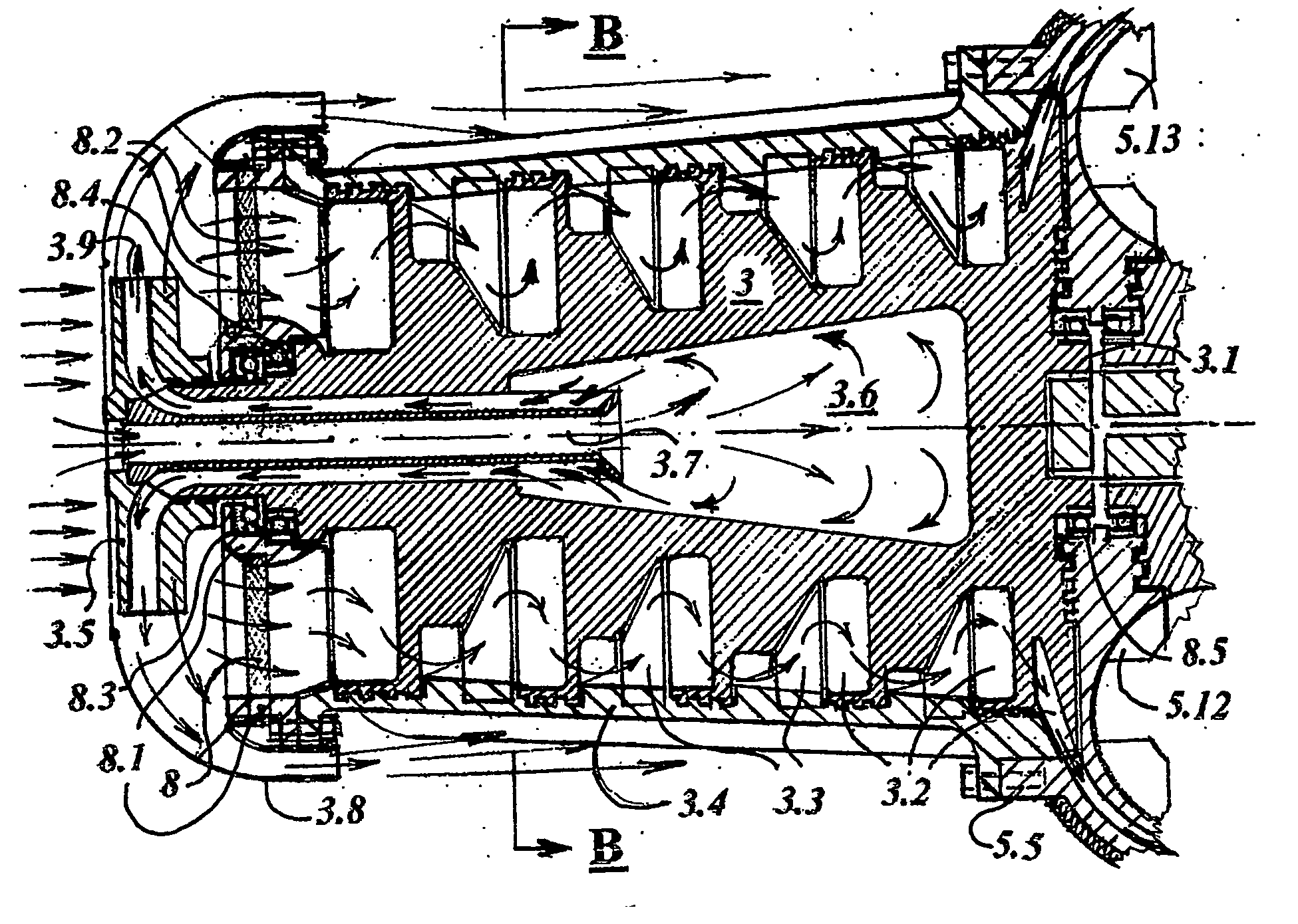
[0026] A hollow impeller 3.5 as in FIG. 1 and FIG. 2 consist the blades, which are turned so, that driving an air in axial direction by the centrifugal force would throw out an air carrying heavy fractions as dust. A carrying dust air, for compressor cooling, is directed by a diffuser-shade 3.8, along of the cooling blades on the compressor housing 3.4. At the same time a hollow impeller 3.5, by the channels in the blades 3.9, sucks an air through the outer channels of a cross-pipe 3.7 from the emptiness 3.6, generating vacuum inside of the compression rotor 3. A hollow impeller 3.5 is mounted onto the front end of the compression rotor 3 so, that channels 3.9 in the blades have continuation with the outer channels of a cross-pipe 3.7, located in the center of a compression rotor 3. An ambient air flows through the central channel of a cross-pi...


PUM


Abstract

A rotary internal combustion engine with intermittent burning cycle, converting heat energy into the rotary motion, having a multi stage compression rotor (3) with centrifugally-axial air compression impellers (3.2), valve (5.1), which alternatively filling up the combustors (4.3) with the compressed air and closing them. A fuel pump (6) compresses fuel and through fuel distributor (6.1) supplies it to the combustors (4.3) to achieve combustion when sprinkled on the hot-red spirals of the ignition plugs (4.5). The gas generated in the combustors (4.3) passes through a cascade turbines (5.10; 5.3; 5.11), driving the power rotor (5) and through the coupling-gear (5.4) transfering rotary motion to a drive shaft (7). A hollow impeller (3.5), mounted onto the compression rotor (3), pumps air through a diffusor-shade (3.8) for cooling the compressor from outside.

Description

[0001] This invention relates to gas turbine engines.[0002] The gas turbine engines, known to the applicant, suffer from following disadvantages:[0003] 1. These engines are not stable, because the gas of higher than 1000.degree. C. temperature and a dust inflow with compressed air rapidly destroys the high-speed power and compressor turbines. Therefore, for keeping low gas temperature, need to supply 3-4 times larger amount of air than it need for burning. With the improvement of air filtering considerably grows volume of the engine and consumption of energy.[0004] 2. Low efficiency (only about 30%), because for compressing required amount of air consumes 2 / 3 of energy, generating by the engine.[0005] 3. The cooling losses and thermal losses with an exhaust 1.16 times higher than losses of a diesel.[0006] 4. Bad stopping, what is unacceptable for the automobiles.[0007] In SU (Russia) patent No 293471 A1 is described a gas turbine engine comprising the low pressure axial and the high...

Claims


Application Information

Patent Timeline
Patent Type & Authority Applications(United States)
IPC IPC(8): F02C5/02F23R7/00F02C5/12F02C6/20F02C7/224F04D29/08F04D29/30F04D29/38
CPCF02C5/02F02C6/20F02C5/12
Inventor STANEVICIUS, ALGIMANTAS ALEKSANDRAS
Owner STANEVICIUS ALGIMANTAS ALEKSANDRAS
Why Eureka
Try Eureka