
Jacketed LED assemblies and light strings containing same

a technology of led assemblies and light strings, applied in semiconductor devices, non-electric lighting, lighting and heating apparatus, etc., can solve the problems of low cost, reduced light flashing, and very long life of leds, so as to minimize peak current draw and reduce the amount of light flashing

Inactive Publication Date: 2004-08-26
FIBER OPTIC DESIGNS
View PDF22 Cites 37 Cited by
  • Summary
  • Abstract
  • Description
  • Claims
  • Application Information

AI Technical Summary

Benefits of technology

[0061] For jacketing, or over-molding LED lamps one first determines the TG temperature of the encapsulating epoxy used. Second, the mold temperature and duration of the injection (jacketing) process are adjusted so the TG temperature is not exceeded. Pre-warming the injection material (PVC, PP, PS, etc.) in its raw granular, or pellet form will greatly assist material flow, reduce air pockets, or voids in the finished jackets, as well as reduce molding duration and temperature.
[0089] Many current-limiting designs use a single impedance element in series between the LED network and the power supply. Current-saturated transistors are a less common method of current limiting. A resistor is often used for the impedance element due to low cost, high reliability and ease of manufacture from semiconductors. For pulsed-DC or AC power, however, a capacitor or inductor may instead be used for the impedance element. With AC power, even though the waveform shape may be changed by capacitors or inductors, the overall effect of these reactive elements is basically the same as a resistor, in adding constant impedance to the circuit due to the single AC frequency involved (e.g., 60 Hz). In any case, the fundamental effect of current-limiting circuitry is to partially linearize or limit the highly nonlinear current versus voltage characteristic response curve of the diode, as shown in FIG. 7 for a single resistor element.

Problems solved by technology

First, as part of an assembly, LEDs have a very long lifespan, compared with common incandescent and fluorescent sources.
Fourth, with newer doping techniques, LEDs are becoming increasingly efficient, and colored LED sources currently available may consume an order of magnitude less power than incandescent bulbs of equivalent light output.
Moreover, with expanding applications and resulting larger volume demand, as well as with new manufacturing techniques, LEDs are increasingly cost effective.
LED contacts are also available in copper or copper-alloys, although these materials generally are considered undesirable because of their higher cost and incompatibility with some automated LED manufacturing equipment and certain types of LED die material.
Although manufacturers take efforts to seal the contacts and connections against moisture and airborne contaminants, it is difficult if not impossible to achieve completely and consistently a moisture and contaminant seal.

Method used


Image

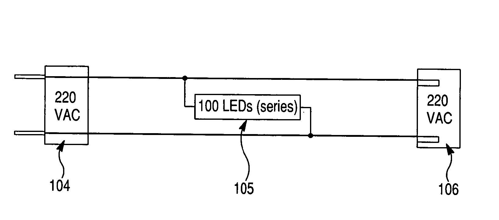
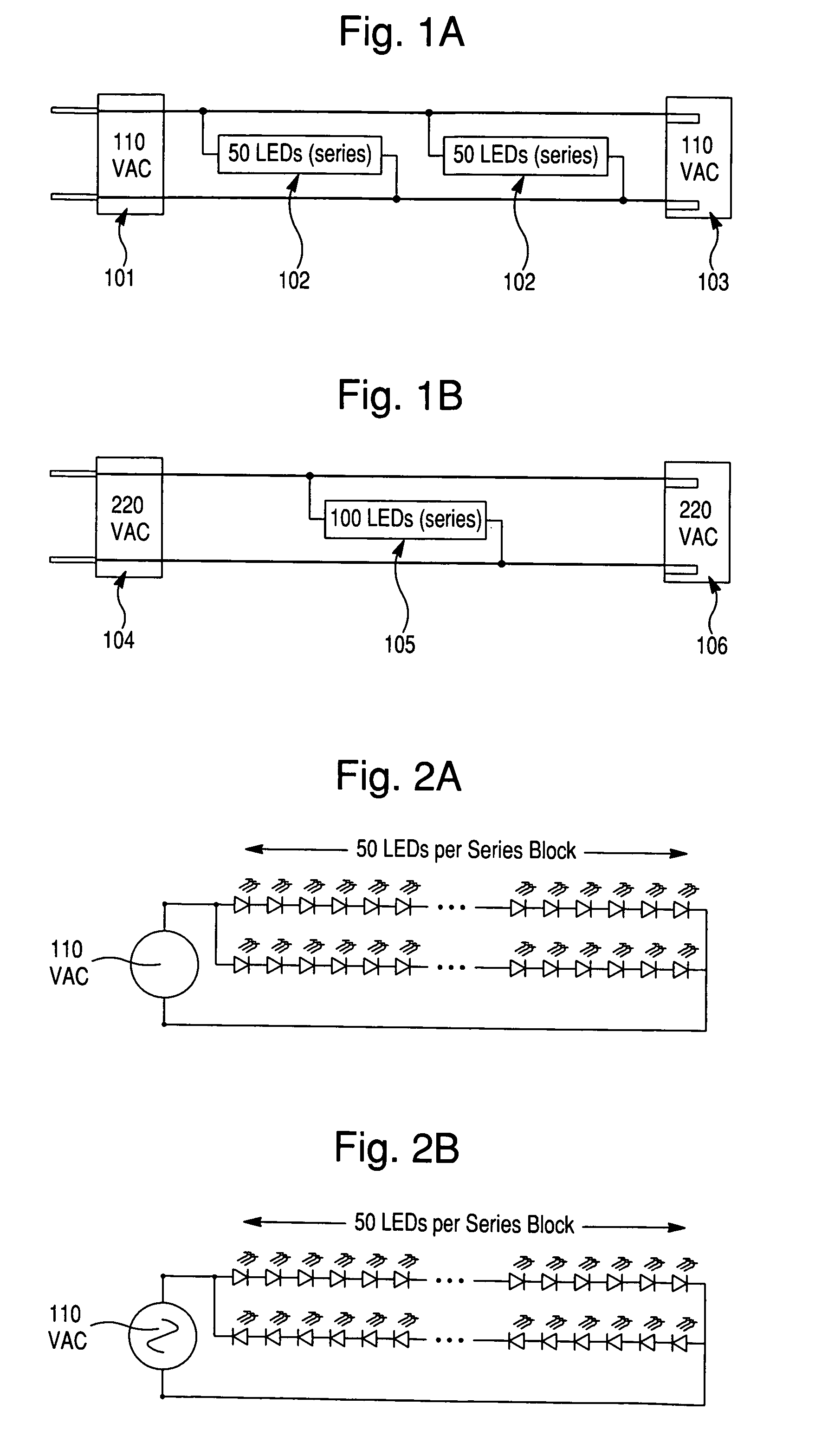
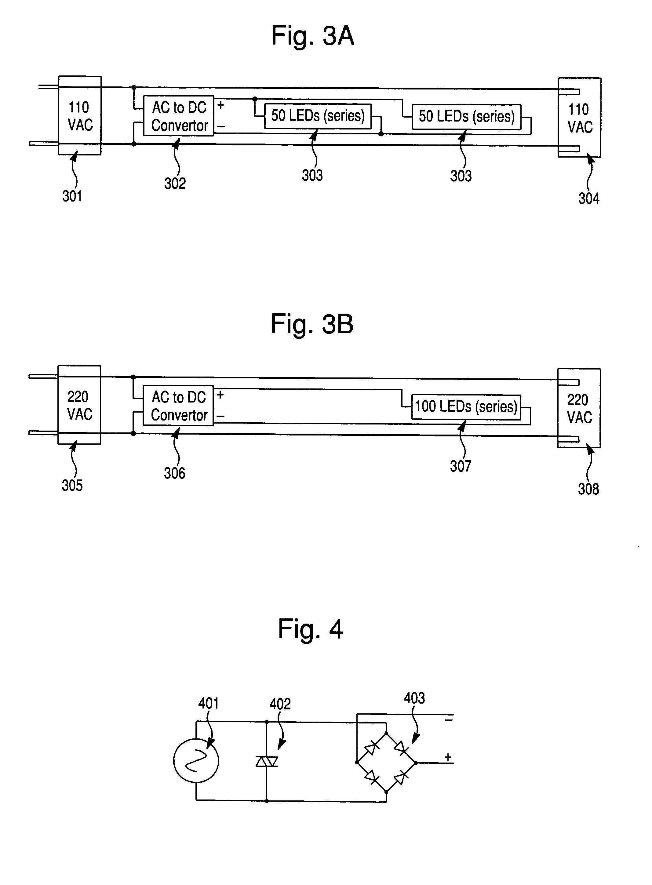
  • Jacketed LED assemblies and light strings containing same
  • Jacketed LED assemblies and light strings containing same
  • Jacketed LED assemblies and light strings containing same

Examples


Embodiment Construction

[0041] Reference will now be made in detail to the presently preferred embodiments and methods of the invention as illustrated in the accompanying drawings, in which like reference characters designate like or corresponding parts throughout the drawings. It should be noted, however, that the invention in its broader aspects is not limited to the specific details, representative assemblies and methods, and illustrative examples shown and described in this section in connection with the preferred embodiments and methods. The invention according to its various aspects is particularly pointed out and distinctly claimed in the attached claims read in view of this specification, and appropriate equivalents.

[0042] It is to be noted that, as used in the specification and the appended claims, the singular forms "a," "an," and "the" include plural referents unless the context clearly dictates otherwise.

[0043] According to an embodiment of the present invention, a jacketed light emitting diode...


PUM


Abstract

A jacketed light emitting diode assembly is provided, which includes a light emitting diode including a set of positive and negative contacts, and a lens body containing a semiconductor chip and end portions of the contacts. An electrical wire set of first and second electrical wires are connected to the positive contact and the negative contact, respectively. A light transmissive cover receives the lens body, and has an opening through which at least one of the contact set and the electrical wire set passes. An integrally molded plastic jacket at the opening of the light transmissive cover provides a seal at the opening against moisture and airborne contaminants. A waterproof light string including one or more of the jacketed light emitting diode assemblies is also provided, as are related methods.

Description

[0001] This application is a Continuation-In-Part of U.S. patent application Ser. No. 10 / 243,835 filed Sep. 16, 2002, which is a Continuation of U.S. patent application Ser. No. 09 / 819,736 filed Mar. 29, 2001, now U.S. Pat. No. 6,461,019.[0002] 1. Field of Invention[0003] The present invention relates to light emitting diode assemblies, light strings comprising a plurality of light emitting diode assemblies, and related methods.[0004] 2. Description of Related Art[0005] Light emitting diodes (LEDs) are increasingly employed as a basic lighting source in a variety of forms, including decorative lighting, for reasons among the following. First, as part of an assembly, LEDs have a very long lifespan, compared with common incandescent and fluorescent sources. For example, a typical LED lifespan is at least 100,000 hours. Second, LEDs have several favorable physical properties, including ruggedness, cool operation, and ability to operate under wide temperature variations. Third, LEDs are...

Claims


Application Information

Patent Timeline
Patent Type & Authority Applications(United States)
IPC IPC(8): F21S4/00H01L33/58H05B33/02H05B44/00
CPCF21W2121/00F21V23/001F21V31/005Y02B20/383H01L33/58H05B33/0809F21W2121/04H05B33/0803Y10S362/80H05B33/0821H01L2924/30107F21S4/001F21V5/04H01L2224/48247F21Y2101/02F21V31/04F21V15/01H01L2924/3011F21V19/0005H01L2224/48091H01L2924/00014H01L2924/00H01L2924/181F21Y2115/10F21S4/10H05B45/40H05B45/37Y02B20/30H05B45/42H01L2924/00012H01L33/56H01L33/62
Inventor ALLEN, DAVID
Owner FIBER OPTIC DESIGNS
Learn More