
Non-evaporation type getter, display unit and production method for them

a technology of evaporation type and getter, which is applied in the manufacture of electrode systems, electric discharge tubes/lamps, and tubes with screens, etc., can solve the problems of shortening the life of the fed, affecting the effect of masking, and affecting the effect of voltage resistance characteristics between substrates

Inactive Publication Date: 2004-09-02
SONY CORP
View PDF1 Cites 21 Cited by
  • Summary
  • Abstract
  • Description
  • Claims
  • Application Information

AI Technical Summary

Benefits of technology

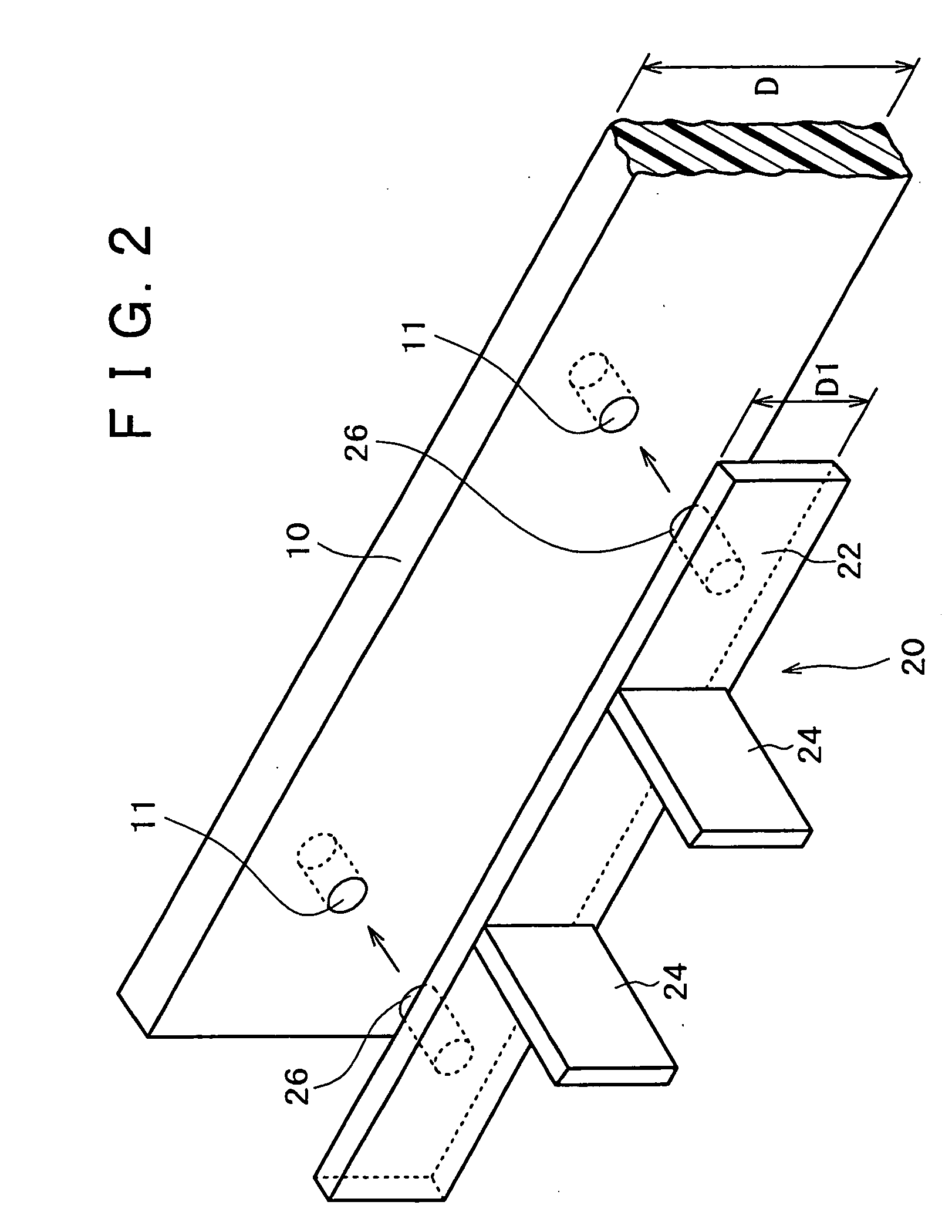
[0015] The non-evaporation type getter according to the present invention is comprised of the molded body formed by powder injection molding, and, therefore, can have a very complicated shape, as compared with non-evaporation type getters produced by a conventional powder sintering technique (for example, the powder press sintering technique disclosed in Japanese Patent Laid-open Nos. Hei 8-225806 and Hei 5-159697). This is due to the fact that, in the powder injection molding, a kneaded mixture containing a metallic powder as a principal constituent can be injected into a mold having a complicated shape. In addition, even a molded body having a complicated shape has a shrinkage factor upon sintering which is comparatively stable at all portions, has a sufficient mechanical strength as a structure body to be mounted in a gas-tight container of a display apparatus such as a flat panel display apparatus, and is free of such problems as dusting.
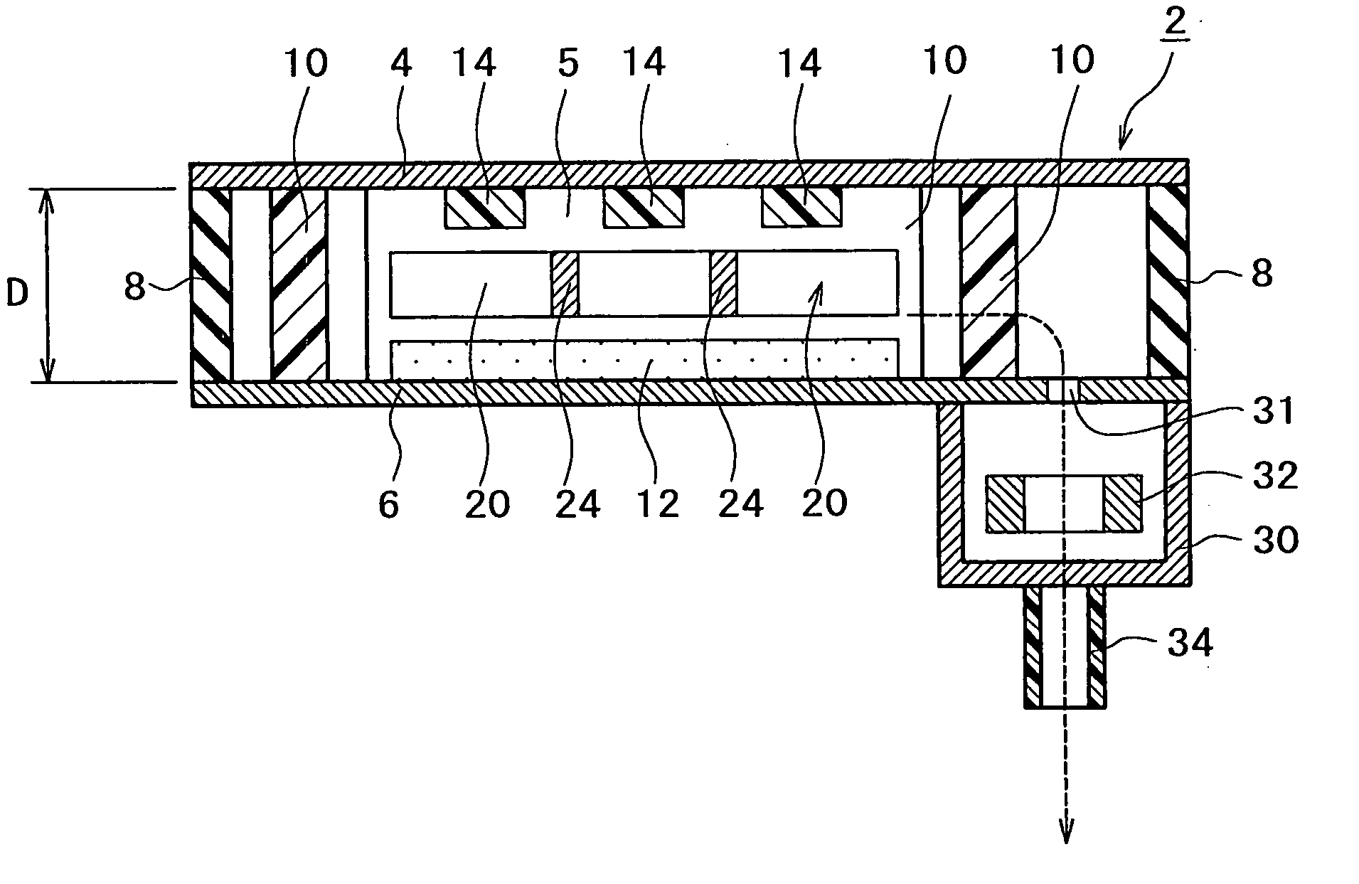
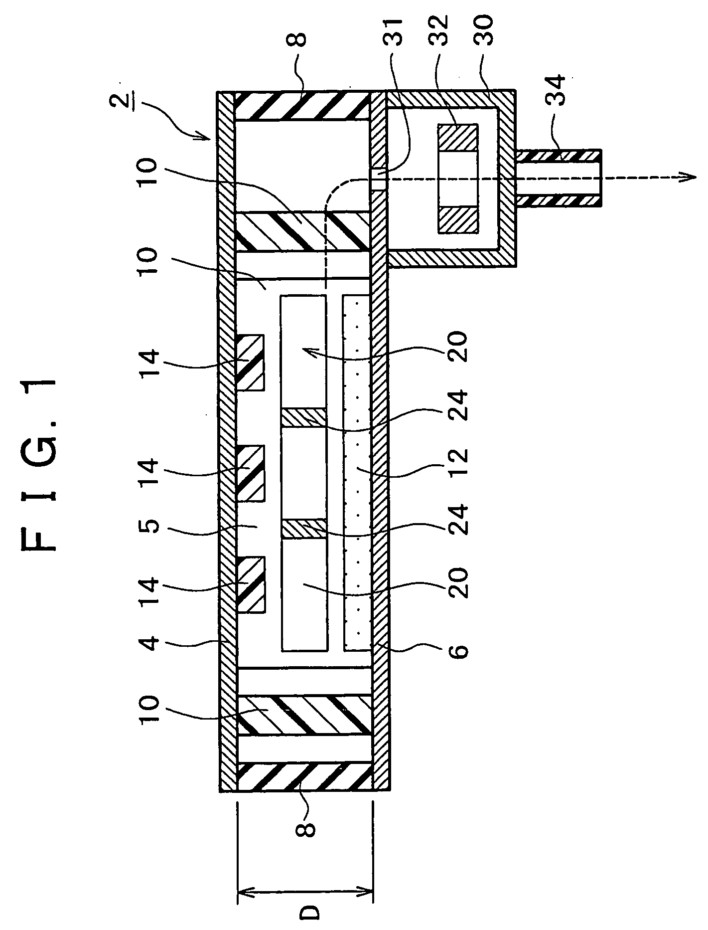
[0094] Besides, in this embodiment, the non-evaporation type getters 20 are arranged at such positions as not to hinder the emission of electron beams from the electron emission source layer 12 toward the phosphors 14 and not to be connected directly to the front substrate 4 and the back substrate 6. The adoption of such a floating structure in which the non-evaporation type getters are not in direct contact with the back substrate provided with the electron emission sources and the front substrate including the phosphors ensures that the voltage resistance characteristic between the substrates is not deteriorated. Incidentally, in the flat panel display apparatus 2 such as an FED, a high voltage of about 5 kV, for example, is impressed between the substrates.

Problems solved by technology

This is because, at a lower degree of vacuum (namely, at a higher pressure), field emission devices used as the electron emission sources are contaminated, leading to a trouble regarding the electron emission characteristics (emission characteristics), and to shorten the life of the FED.
When a gradient of the degree of vacuum is generated as a result of the liberation of a gas or gases, in the region where the field emission devices are formed on the back substrate the field emission devices may be contaminated depending on the location, and the emission characteristics at the contaminated portions are degraded, resulting in a shortening of the life of the FED.
Therefore, with only the vapor deposition type getter disposed only at an end portion of the gas-tight container, generation of a gradient of the degree of vacuum cannot be obviated.
In the formation of the non-evaporation type getters, it is necessary to form the non-evaporation type getters at positions for avoiding the field emission device pattern and the phosphor pattern, resulting in a difficulty on a manufacturing process basis that an accurate masking treatment is needed.
If the masking is unsatisfactory and the field emission devices are contaminated due to vapor deposition or the like, a trouble as to emission characteristics is generated, and the life of the flat panel display apparatus such as the FED is shortened.
According to the method disclosed in the publication, however, cracking or deformation is liable to occur at the time of sintering due to such causes as a distribution of shrinkage factor, so that there is the limitation that it is impossible to form a non-evaporation type getter having a complicated shape.
Besides, the powder molding leads to the problem of dusting.
In the method, however, it is difficult to achieve masking at the time of applying the adhesive.
Besides, depending on the kind of the adhesive, a gas may be liberated from the adhesive during or after a thermal activating treatment of the getter, leading to a lowering of the gas absorbing capability of the getter or to contamination of the field emission devices, with the result of degradation of the emission characteristics.
Thus, particularly in a flat panel display apparatus, it has been very difficult to dispose the non-evaporation type getter.

Method used


Image

  • Non-evaporation type getter, display unit and production method for them
  • Non-evaporation type getter, display unit and production method for them
  • Non-evaporation type getter, display unit and production method for them

Examples


example 1

[0103] In powder injection molding, first, a metallic powder including elemental Ti as a principal constituent and a binder were kneaded with each other, to prepare an injection molding material. The average grain diameter of the metallic powder was 10 to 20 .mu.m. Besides, as the binder, a paraffin-propylene based binder was used.

[0104] Next, the powder injection molding material was injected into a mold having a cavity in the shape of the non-evaporation type getter 20c shown in FIG. 4C, to form a pre-molded body. Then, the binder contained in the pre-molded body was removed. The process up to this stage was carried out under the same conditions as in the ordinary powder injection molding.

[0105] Subsequently, the pre-molded body was baked, to obtain a molded body composed of a sintered body. The baking temperature was 900.degree. C. The porosity of the molded body after sintering was 25%. An electron microphotograph of the molded body after sintering is shown in FIG. 6A.

[0106] Nex...

example 2

[0112] A vapor-deposited film composed singly of Zr was formed by an electron beam vapor deposition process on the surface of the sintered body getter obtained in Example 1, and the resulting getter was subjected to the same gas absorbing capability test as in Example 1. The thickness of the vapor-deposited film was 0.1 .mu.m. The result is represented by curve A4 in FIG. 5B. In addition, an SEM section photograph of the getter thus obtained is shown in FIG. 7.

[0113] As shown in FIG. 5B, the getter obtained in Example 2 showed a further longer life of gas absorbing capability and, as a whole, an enhancement of absorbing capability up to about 10%, as compared with the getter obtained in Example 1.

example 3

[0114] A non-evaporation type getter composed of a sintered body was formed in the same manner as in Example 1, except that the sintering temperature for the molded body was set to 950%. A section photograph of the getter thus obtained is shown in FIG. 6B. It was confirmed that pores can be formed sufficiently by this method.


PUM

PropertyMeasurementUnit
porosityaaaaaaaaaa
grain diameteraaaaaaaaaa
porosityaaaaaaaaaa

Abstract

Disclosed are a non-evaporation type getter excellent in gettering effect, capable of maintaining the inside of a gas-tight container in a display apparatus, particularly a flat panel display apparatus or the like, in a high vacuum condition, easy to mount and less liable to contaminate the inside of the gas-tight container, a display apparatus including the getter, and methods of manufacturing the same. The non-evaporation type getter (20) includes a molded body including at least one element selected from the group consisting of Ti, Zr, Al, V, and Fe as a principal constituent thereof, the molded body formed by powder injection molding. The molded body is composed of a porous body having a porosity of 10 to 30%.

Description

[0001] The present invention relates to a non-evaporation type getter, a display apparatus, and methods of manufacturing the same.[0002] In recent years, there have been proposed flat panel display apparatuses in which phosphors are irradiated with electron beams emitted from electron emission sources such as field emission devices, to cause the phosphors to emit light, thereby forming an image, such as a field emission display (hereinafter abridged to FED).[0003] In an FED, a substrate provided with electron emission sources arranged in a matrix form and a substrate provided with phosphors are disposed opposite to each other with a minute gap therebetween, the peripheries of the substrates are sealed to form a gas-tight container, the inside of the gas-tight container is maintained in a high vacuum or ultrahigh vacuum, and the phosphors are irradiated with electron beams emitted from electron emission sources, to cause the phosphors to emit light, thereby displaying an image.[0004]...

Claims


Application Information

Patent Timeline
Patent Type & Authority Applications(United States)
IPC IPC(8): B22F3/02B01J20/02B22F3/11B22F3/22B22F3/24H01J7/18H01J9/24H01J9/39H01J29/87H01J29/94H01J31/12
CPCB01J20/02B01J20/0211B01J20/0214B01J20/0229B01J20/0248B22F3/11B22F3/225H01J29/94B22F2998/00H01J7/18H01J7/183B01J20/3007B01J20/3204B01J20/3236
Inventor HASEGAWA, YOJI
Owner SONY CORP
Learn More