Lithographic apparatus and method of manufacturing a device

a technology of lithographic projection and manufacturing method, which is applied in the direction of engine lubrication, liquid/fluent solid measurement, radiation therapy, etc., can solve the problems of mask deformation, overlay errors, lack of rigidity and stiffness,

Inactive Publication Date: 2004-09-16
ASML NETHERLANDS BV
View PDF6 Cites 10 Cited by
  • Summary
  • Abstract
  • Description
  • Claims
  • Application Information

AI Technical Summary

Problems solved by technology

Previous clamping arrangements, such as a rigid vacuum clamp, have the problem that deformation of the mask can be caused.
This can be as a result of either or both of the mask and the vacuum clamp not being perfectly flat or because of contaminant particles being trapped between the mask and the clamp.
The deformation of the mask or substrate leads to distortion of the exposed image which can lead to overlay errors.
However, this still suffers from the problem of co...

Method used


Image

  • Lithographic apparatus and method of manufacturing a device
  • Lithographic apparatus and method of manufacturing a device

Examples


Embodiment Construction

[0028] In the Figures, corresponding reference symbols indicate corresponding parts.

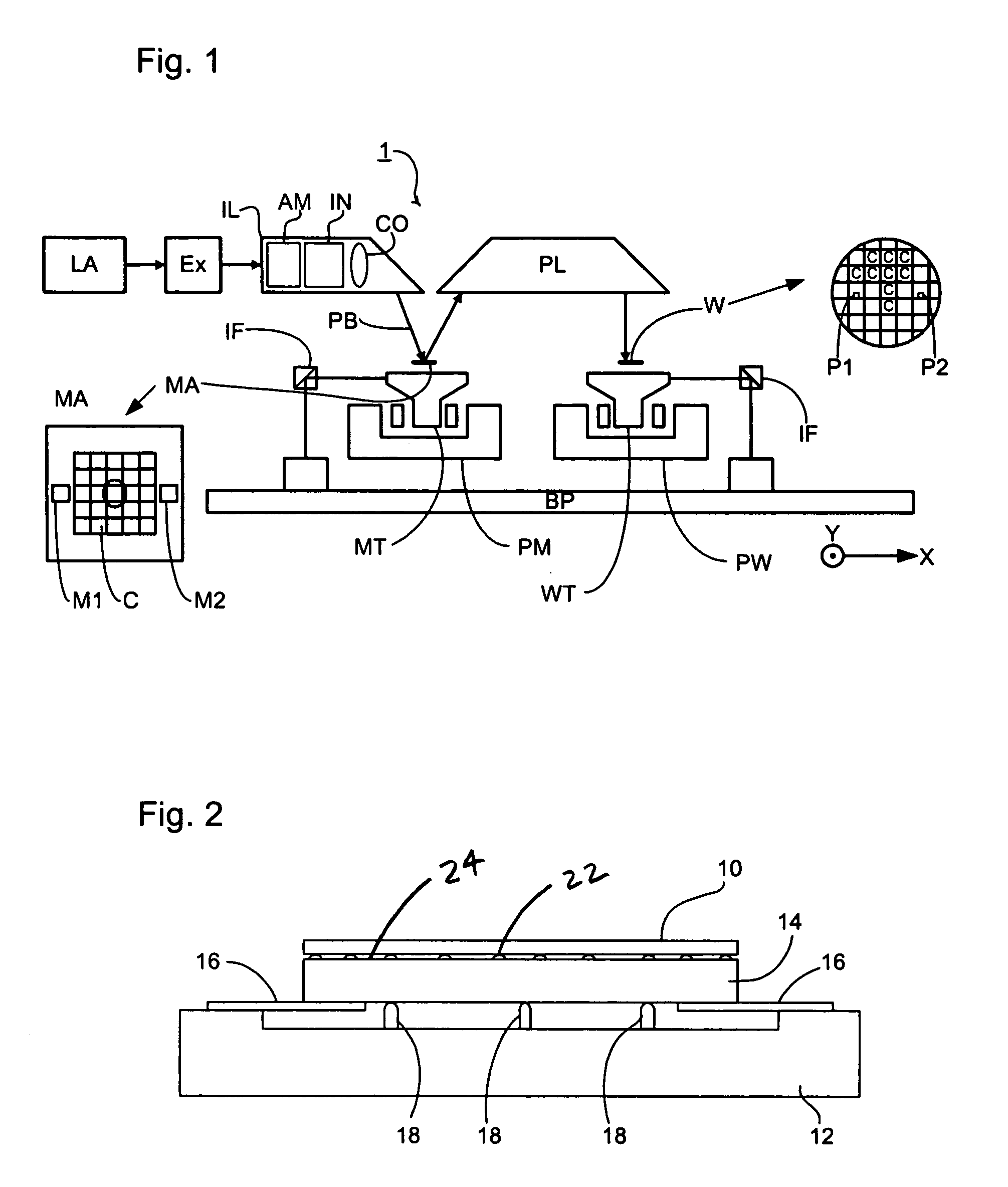
[0029] FIG. 1 schematically depicts a lithographic projection apparatus according to an embodiment of the invention. The apparatus comprises: a radiation system Ex, IL, for supplying a projection beam PB of radiation (e.g. EUV radiation), which in this particular case also comprises a radiation source LA; a first object table (mask table) MT provided with a mask holder for holding a patterning device, illustrated in the form of the mask MA (e.g. a reticle), and connected to first positioning structure for accurately positioning the mask with respect to item PL; a second object table (substrate table) WT provided with a substrate holder for holding a substrate W (e.g. a resist-coated silicon wafer), and connected to second positioning structure for accurately positioning the substrate with respect to item PL; a projection system ("lens") PL (e.g. mirror group) for imaging an irradiated portion of the ...


PUM


Abstract

A lithographic projection apparatus includes a radiation system for providing a beam of radiation and a support structure for supporting a patterning device. The patterning device serves to pattern the beam according to a desired pattern. The lithographic projection apparatus includes a substrate table for holding a substrate and a projection system for projecting the patterned beam onto a target portion of the substrate. At least one holding structure includes at least one compliant member holding a pimple plate for holding a removable item for the apparatus.

Description

[0001] The present application claims priority to European Application No. 02258866.9, filed on Dec. 23, 2002, the entirety of which is hereby incorporated into the present application by reference thereto.[0002] 1. Field of the Invention[0003] The present invention relates to a lithographic projection apparatus and a method of manufacturing a device.[0004] 2. Brief Description of Related Art[0005] The term "patterning device" or "patterning structure" as here employed should be broadly interpreted as referring to a device or structure that can be used to endow an incoming radiation beam with a patterned cross-section, corresponding to a pattern that is to be created in a target portion of the substrate; the term "light valve" can also be used in this context. Generally, the pattern will correspond to a particular functional layer in a device being created in the target portion, such as an integrated circuit or other device (see below).[0006] An example of such patterning device inc...

Claims


Application Information

Patent Timeline
IPC IPC(8): G03F7/20H01L21/027H01L21/683
CPCG03F7/707H01L21/027
Inventor GILISSEN, NOUD JANLAMBERTUS DONDERS, SJOERD NICOLAASANTONIUS LEENDERS, MARTINUS HENDRIKUS
Owner ASML NETHERLANDS BV
Why Eureka
Try Eureka